SPRUJ51 june 2023
- 1
- 1Abstract
- 2EVM Revisions and Assembly Variants
- Trademarks
-
3System Description
- 3.1 Key Features
- 3.2 Functional Block Diagram
- 3.3 AM62x-Low Power SK EVM Interface Mapping
- 3.4 Power ON OFF Procedures
- 3.5
Peripheral and Major Component Description
- 3.5.1 Clocking
- 3.5.2 Reset
- 3.5.3 OLDI Display Interface
- 3.5.4 CSI Interface
- 3.5.5 Audio Codec Interface
- 3.5.6 HDMI Display Interface
- 3.5.7 JTAG Interface
- 3.5.8 Test Automation Header
- 3.5.9 UART Interface
- 3.5.10 USB Interface
- 3.5.11 Memory Interfaces
- 3.5.12 Ethernet Interface
- 3.5.13 GPIO Port Expander
- 3.5.14 GPIO Mapping
- 3.5.15 Power
- 3.5.16 AM62x-Low Power SK EVM User Setup and Configuration
- 3.5.17 Expansion Headers
- 3.5.18 Push Buttons
- 3.5.19 I2C Address Mapping
- 4Known Issues and Modifications
- 5Revision History
- 6IMPORTANT NOTICE AND DISCLAIMER
3.4.1 Power-On Procedure
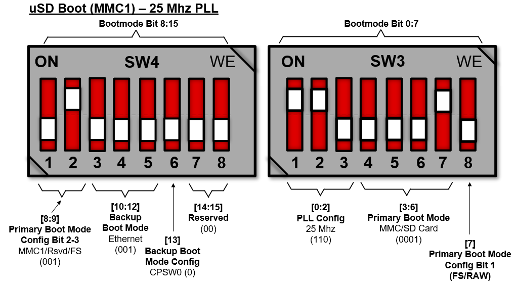
- Place the SK EVM boot switch selectors (SW3, SW4) into selected boot mode. Example boot-modes for SD card is shown below.
- Connect your boot media (if applicable).
- Attach the PD capable USB Type-C cable to the SKEVM Type-C (J13 or J15) Connector.
- Connect the other end of the Type-C cable to the source, either AC Power Adapter, or Type C source device (such as a Laptop computer).
- Visually inspect that either LD8 or LD9 LED should be illuminated.
- XDS110 JTAG and UART debug console output are routed to micro-USB ports J18 and J17, respectively.
 Figure 3-5 Example SD Boot Mode