SPRUJE4A August 2024 – November 2024 F29H850TU , F29H859TU-Q1
- 1
- Description
- Get Started
- Features
- 5
- 1Evaluation Module Overview
- 2Hardware
- 3Software
- 4Hardware Design Files
- 5Additional Information
- 6References
- 7Revision History
2.8 Debug Information
This section describes frequently asked questions about the F29H85X-SOM-EVM.
- Can other programming and debug tools (such as an
XDS200 debug probe) be used with the controlSOM?
- Yes, when the controlSOM is paired with the HSEC180ADAPEVM adapter board and the TMDSHSECDOCK baseboard docking station, a debug probe such as the XDS200 can be used. Also, an XDS560v2 debug probe with a MIPI-60 connector can connect directly to the DLT header (J5) on the controlSOM.
- Why can't I connect to the controlSOM in Code
Composer Studio?
- Ensure there is power on the controlSOM by verifying that LED1 (5.0-V input) and LED2 (3.3-V output) are on.
- Check that power is being delivered to the F29H85x device by probing TP1 (VDD, 1.25-V), TP2 (VDDIO, 3.3-V), and TP14 (VDDA, 3.3-V).
- Check that the F29H85x device is out of reset by probing TP15. This test point should read close to 3.3-V when the device is out of reset.
- If using Section 2.1.2 or Section 2.1.3, check that the XDS110ISO-EVM is configured for full JTAG mode. Switch S1 on the XDS110ISO-EVM should be set to the JTAG setting.
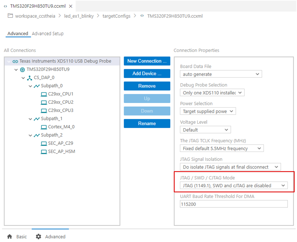
- Ensure that the target configuration is set up to use full JTAG mode. Open the Target Configuration file (.ccxml) in Code Composer Studio. Click on the Advanced tab and select "JTAG (1149.1), SWD and cJTAG are disabled" from the "JTAG/SWD/cJTAG Mode" drop-down. Alternatively, a working target configuration file is included in all the F29 SDK examples. This file can be used without modifications.
 Figure 2-14 Target Configuration Advanced
Options