SPRUJE4A August 2024 – November 2024 F29H850TU , F29H859TU-Q1
- 1
- Description
- Get Started
- Features
- 5
- 1Evaluation Module Overview
- 2Hardware
- 3Software
- 4Hardware Design Files
- 5Additional Information
- 6References
- 7Revision History
3.4 Developing an Application
A sample application can be built, loaded, and ran on the EVM once the MCU_SDK_F29H85x and CCS Theia have been installed.
Follow these steps to load a simple LED blinking example on the F29H85x controlSOM:
- Set the controlSOM in flash boot mode
- Set switch S1 (GPIO84) to 1
- Set switch S1 (GPIO72) to 1
- Set up the controlSOM and XDS110ISO-EVM in Stanalone configuration (see Section 2.1.1)
- Power on the EVMs
- Launch CCS Theia
- Go to "File -> Import Project(s)"
- Click "Browse.." and navigate to the path below, then click "Select Folder":
- C:\ti\mcu_sdk_f29h85x_X_XX_XX_XX_\examples\driverlib\single_core\led\led_ex1_blinky
- Select the "led_ex1_blinky" project from the "Discovered Projects" list and click "Finish" to import the project into the workspace
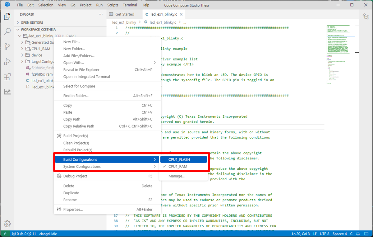
- Right-click on the project name
and select "Build Configurations -> CPU1_FLASH"
 Figure 3-1 Build Configuration
Selection
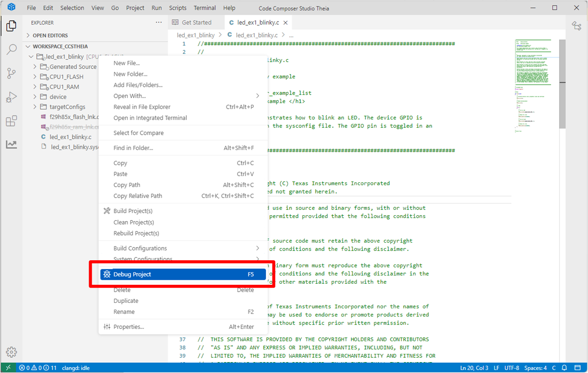
 - Right-click on the project name
and select "Debug Project (F5)". This builds the project, executes the "post
build sequence for FLASH configuration", and launches the target
configuration.
 Figure 3-2 Debug Project
Selection
 - Select "Texas Instruments XDS110 USB Debug Probe_0/C29xx_CPU1" as the core
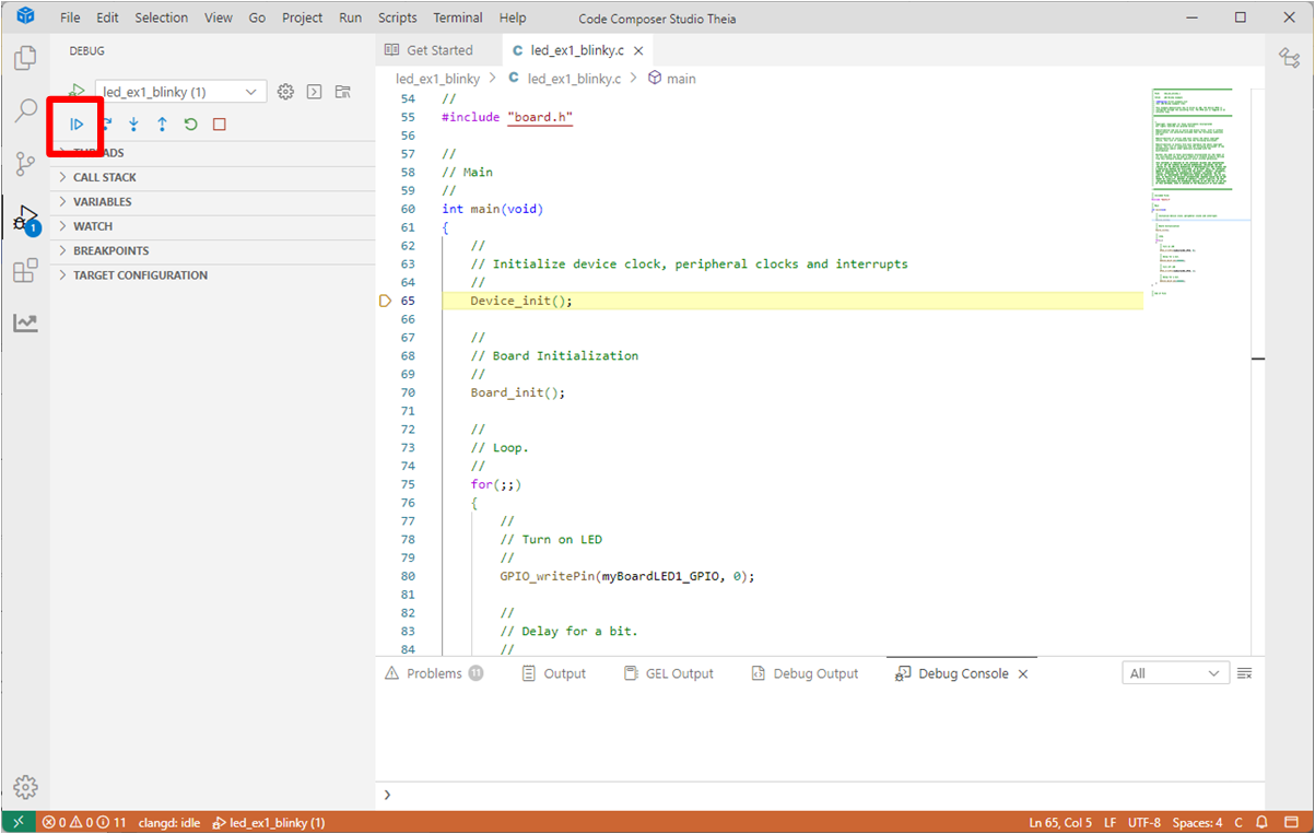
- Navigate to Debug (left side of
screen) and select the blue play button to run the example
 Figure 3-3 Run Selection
 - Observe the LED blinking on the controlSOM