SPRUJF1 November 2024 AM2612
ADVANCE INFORMATION
- 1
- Description
- Key Features
- 1LaunchPad Module Overview
-
2Hardware Description
- 3.1 Board Setup
- 3.2 Functional Block Diagram
- 3.3 GPIO Mapping
- 3.4 Reset
- 3.5 Clock
- 3.6 Memory Interfaces
- 3.7 Ethernet Interface
- 3.8 I2C
- 3.9 Industrial Application LEDs
- 3.10 SPI
- 3.11 UART
- 3.12 MCAN
- 3.13 FSI
- 3.14 JTAG
- 3.15 TIVA and Test Automation Pin Mapping
- 3.16 LIN
- 3.17 ADC and DAC
- 3.18 EQEP and SDFM
- 3.19 EPWM
- 3.20 USB
- 3.21 BoosterPack Headers
- 3Known Issues and modifications done on LP-AM261 RevE1
- 4Additional Information
- 5References
- 6Revision History
2.1.3 Boot mode Selection
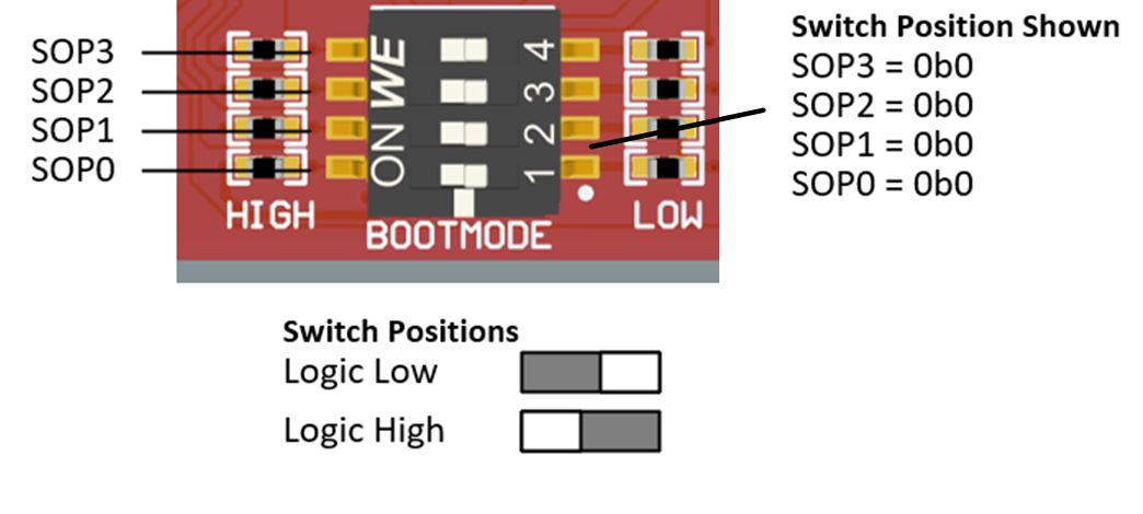
The boot mode for the AM261x is selected by a DIP (Dual In-Line Package) switch (SW4) or the test automation header. The test automation header uses an I2C expansion buffer to drive the boot mode when PORz is toggled. The supported boot modes are shown in Table 2-5. The DIP Switch configurations for each boot mode are shown in Table 2-5. As seen in the schematic, enabling a switch pulls the respective pin to GND through a 1kΩ resistor.

Figure 2-6 Boot mode DIP Switch Positions - LP AM261x E2 SW1 SOP Switches
Table 2-5 Supported Bootmodes and
Bootmode Selection
| SOP3 | SOP2 | SOP1 | SOP0 | Bootmode | ROM Activity | LaunchPad Switch Config |
|---|---|---|---|---|---|---|
| 0 | 0 | 0 | 0 | OSPI-OSPI (4S), 50MHz, SDR, 0x6B | ROM configures OSPI controller in OSPI 4S mode and downloads image from external flash, supports UART fallback boot mode if any failures | 1111 |
| 0 | 0 | 0 | 1 | UART, XMODEM, 115200bps | ROM configures UART0 with baud rate of 115200 bps and downloads image from external PC terminal using x-modem protocol | 1110 |
| 0 | 0 | 1 | 0 | OSPI-OSPI (1S), 50MHz, SDR, 0x0B | ROM configures OSPI controller in OSPI 1S mode and downloads image from external flash, supports UART fallback boot mode if any failures | 1101 |
| 0 | 0 | 1 | 1 | OSPI (8S), SDR, 33 MHz, 0x8B | ROM configures OSPI controller in 8S mode and downloads image from external flash, supports UART fallback boot mode if any failures | 1100 |
| 1 | 0 | 1 | 1 | DevBoot | To support SBL development, R5-will come up with ROM eclipsed, PLLs are initialized, No L2, TCMA and TCMB PBIST are performed, No L2 and TCM memInit. Supported only on FS devices | 0100 |
| 1 | 1 | 0 | 0 | xSPI (1S->8D), 20 MHz, SFDP | ROM configures OSPI controller in xSPI 8D mode, Reads SFDP table for read command and downloads image from external flash, Flashes with SFDP are of JEDEC standard Rev D only supported. In case of any failure it falls back to UART boot mode | 0011 |
| 1 | 1 | 1 | 0 | USB DFU | ROM configures USB controller to work in device mode and download the image into L2 memory to process. In case of any failure it falls back to UART boot mode. Supports USB 2.0 device mode at High-Speed (HS, 480 Mbps) | 0001 |
| 1 | x | x | x | Unknown Boot mode | Treated as unknown Boot mode, System gets Panic and waits for watchdog to reset | 0xxx |