SPRZ574 December 2023 AM62P , AM62P-Q1
i2097
DSS: Disabling a Layer Connected to Overlay May Result in Synclost During the Next Frame
Details:
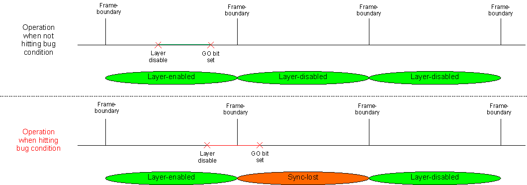
Disabling a layer (for example VID1) connected to an OVR (that is toggling DSS_VID_ATTRIBUTESx[0] ENABLE from 1 to 0) may result in synclost during the next frame. The synclost may result in a corrupted or blank frame (all pixel data sent out of DSS during the frame is 0x0). The occurrence of synclost is dependent on the timing of setting the GO bit (that is DSS_VP_CONTROL[5] GOBIT to 1) vis-à-vis the disabling of the layer. If the “disable layer” MMR write operation and “set GO bit” MMR write operation happens within the same frame boundary, no synclost occurs. If the operations happen across the frame boundary, then synclost occurs (for one frame). The design automatically recovers and returns to normal operation from the next frame after GO bit is set, see Figure 2-1.
 Figure 2-1 Bug Condition
Workaround(s):
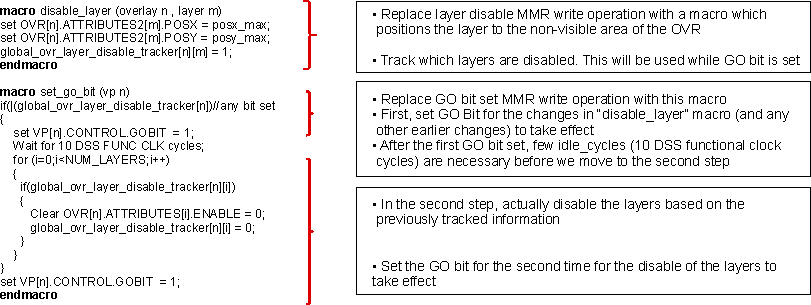
A simple software workaround exists. In the workaround, prior to disabling a layer on the OVR, it is moved to the “non-visible” area of the OVR (for example: DSS_OVR_ATTRIBUTES_x[17-6] POSX = max_value_of_posx or DSS_OVR_ATTRIBUTES_x[30-19] POSY = max_value_of_posy). This avoids the synclost when the layer is disabled.
A sample software workaround pseudo-code is shown on Figure 2-2. In this case, the regular “disable layer” MMR write operation and “set GO bit set” MMR write operation are replaced with macros which implement the software workaround.
 Figure 2-2 Workaround Pseudo-code