SSZT229 november 2020 BQ25731 , BQ25792 , TPS25750
Upal Patel co-authored this article.
A USB Type-C® port with USB Power Delivery (PD) is becoming the standard port for charging single- and multi-cell battery-powered devices. Applications such as wireless speakers, power banks and power tools have been transitioning from proprietary charging ports, legacy USB ports and barrel-jack ports to a standardized USB PD port. USB PD offers a universal alternative for fast and convenient charging, removing the need for users to carry around several adapters or cables with them – helping design engineers create smaller applications with faster charging and fewer components.
As these applications become more feature-rich, compact and power-hungry, it becomes necessary to deliver more power in a smaller solution size. Concurrently, consumers are beginning to expect USB Type-C on their new devices. But implementing a USB PD port has historically been quite challenging for product developers.
Simplifying your design challenge
Programming the MCU to interface between the USB PD controller and battery charger is usually not the only firmware development required when adding USB PD. Typical PD controller ICs require some form of firmware development to configure the PD controller behavior itself, such as compiling some code or scripting functions together. Configuring the USB PD controller is necessary in order to ensure that the settings on the PD controller meet your system requirements, including which voltages and currents the system can sink and which ones it can source.
Designing with TI controllers and chargers
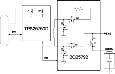
The TPS25750 and BQ25792 integrate all of the power paths required for the battery charger and USB PD controller. Figure 1 highlights how these devices simplify the implementation of a USB PD port for battery-powered systems up to 45 W. When using these two ICs together, the USB PD port will be able to support bidirectional power to both source and sink power, thus enabling the system to charge or be charged from the USB PD port when attached to an external device like a laptop, smartphone, headphones or AC adapter.
In addition to these system implementation benefits, the TPS25750D and BQ25792 integrate all of the system’s field-effect transistors (FETs) and remove the need for an external MCU, enabling you to achieve a very small solution size. When compared to an MCU-based nonintegrated USB PD battery-charging implementation, the typical system solution size is around 150 mm2. When using the TPS2570 and BQ25792, it is possible to achieve a system solution size around 55 mm2.
 Figure 1 TPS25750D and BQ25792 USB PD Battery-charger Implementation
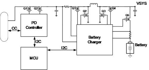
Figure 2 highlights an MCU-based USB PD controller and a battery charger with external FETs for applications requiring high-power charging and system power typically greater than 45 W. For applications greater than 45 W, consider pairing the TPS25750 controller with the BQ25731 charger.
 Figure 2 MCU-based Nonintegrated Solution
Table 1 compares USB PD charging for integrated and nonintegrated MCU-based solutions.
| USB PD battery-charger implementation up to 45 W | MCU-based nonintegrated USB PD battery-charger implementation | |
|---|---|---|
| External MCU | Not required; the TPS25750 is the I2C host controller for the battery charger | Required; the USB PD controller and battery charger operate independently |
| Firmware development | Not required; the system is configurable through a Q&A GUI | Required; necessary to interface with the USB PD controller and battery charger through the MCU |
| System power paths | All system power paths are integrated in the USB PD controller and battery charger | External FETs are necessary to complete the solution |
| Solution size | Approximately 55 mm2 | Approximately 150 mm2 |
The trend toward using USB PD for charging has recently become more urgent, with regulations pushing for universal chargers. Updating your system to charge from USB PD is now easier than ever with the TPS25750 and BQ25792, enabling you to move to the latest universal charging connector while not compromising on solution size.
Additional Resources:
- Read the technical article, "Universal and fast charging - a future trend for battery-powered applications."
- Discover the reference design, "Integrated USB Type-C® power delivery (PD) and charging reference design for 2-4 cell batteries."
- Watch the video, "No firmware development required: New USB Type-C and USB Power Delivery GUI."