SSZT349 january 2020 TPS92610-Q1 , TPS92630-Q1 , TPS92638-Q1
It's incredibly important to indicate a system failure to users, especially when it comes to automotive lighting.
Consider the turn indicator in an automotive rear light, for example, which signals that a driver wants to change lanes or make a turn. A common and growing light source for turn indicators is LEDs, driven by a dual-stage LED driver circuit topology that includes a first-stage buck voltage regulator and a second-stage constant-current linear LED driver. Dual-stage topologies offer the advantage of thermal efficiency.
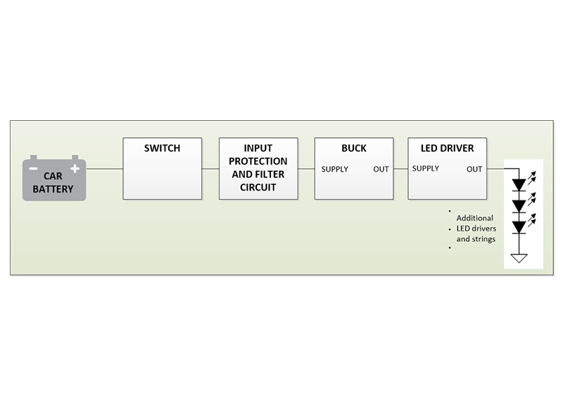
The LED-based turn indicator module shown in Figure 1 comprises a typical automotive battery, switch, input filter, buck regulator and some LED drivers. So what happens if the light stops working? How will you know? Which part of the system failed?
 Figure 1 Turn indicator module
Buck regulator and LED driver integrated circuits implement diagnostic features in order to detect an event against faults. For example, the POWER GOOD signal is a diagnostic feature used to indicate whether or not the output of a buck is in regulation. Similarly, constant-current LED drivers output a FAULT signal to indicate LED short and open circuits.
In this article, I will focus on rear lighting fault circuits and how to combine PWRGD signals from a buck regulator and the FAULT signal from a LED driver to design a fault circuit.
The Buck Converter PWRGD Signal
| Accelerate the evolution of passenger comfort and convenience | |

|
Explore TI's design resources for automotive lighting. |
LED Driver FAULT Signal
- One-fail-all-fail (OFAF): Shuts down all devices and reports a fault if there is a fault in one of the devices.
- Disabled OFAF: When one device has a fault, the remaining devices continue operating and a fault is reported.
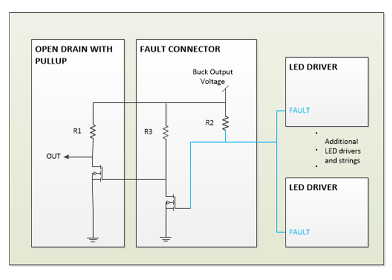
When connecting the FAULT pins of up to 15 devices together, the system uses OFAF. Figure 2 shows the fault connector circuit connected to the FAULT pins of LED drivers. The fault connector circuit is used to improve FAULT signal robustness. The open drain with pullup is used for easy interface with external circuitry.
 Figure 2 Fault Connector
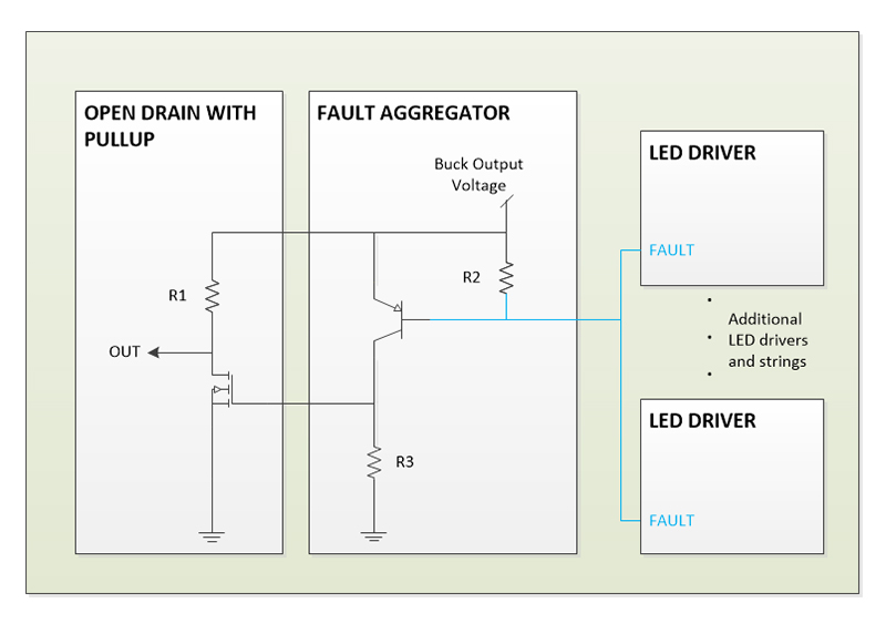
Disabled OFAF requires a fault aggregator circuit. Figure 3 shows the fault aggregator circuit connected to the FAULT pins of LED drivers. The open-drain output with pullup is used to assert OUT low in the event of a fault and high if there is no fault.
 Figure 3 Fault Aggregator
The fault aggregator circuit is defined as a fault pin pullup circuit. In order to disable OFAF, the FAULT pin must be pulled up to maintain a voltage greater than 2 V at all times. The P-channel transistor (PNP) is used to convert the FAULT pin from a current-controlled pin to a voltage. Pullup resistor R2 keeps FAULT greater than 2 V. Typically, a fault signal asserts low in the event of a fault and asserts high if there is no fault. Thus, the open-drain output with pullup inverts the logic of the fault aggregator circuit to assert OUT low in the event of a fault and high if there is no fault. You can omit the open-drain output with pullup from the design if the system requires OUT high in the event of a fault and low if there is no fault.
When a fault is triggered, the LED driver internally pulls down current, and the pulldown current flows through pullup resistor R2. The PNP turns on, the output of PNP goes high and OUT becomes low. When no fault is triggered, the LED driver internally pulls up and PNP acts as an open switch. The output of PNP goes low and OUT becomes high. In both cases, FAULT remains greater than 2 V.
Considering the turn indicator module, the buck regulator output voltage should power the fault aggregator circuit; a Zener diode can clamp the buck regulator output to a lower voltage. In case of a buck regulator failure, there is no power to the fault aggregator, and a fault is indicated.
The “Automotive high side dimming rear light reference design” shows how to design a fault aggregator circuit using TI’s TPS92630-Q1 and TPS92638-Q1.
Using POWER GOOD Signal to Enable an LED Driver
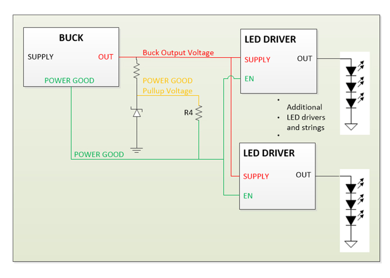
 Figure 4 Connecting POWER GOOD and EN
By connecting the output of the POWER GOOD pin to the EN pin of the LED drivers, the POWER GOOD signal now controls the LED drivers. In normal operation, the POWER GOOD pin asserts high and the LED drivers are enabled. In the case of a buck regulator failure, the POWER GOOD pin l asserts low, the LED drivers are not enabled, the fault aggregator circuit has no power, and OUT becomes low – indicating a fault.
System Fault Analysis
 Figure 5 Disabling OFAF with a Zener Diode and Fault Aggregator
When the system operates normally, the battery voltage is filtered and bucked down to power the LED drivers. The POWER GOOD pin is pulled up to the Zener diode clamping voltage, asserts high and enables the LED drivers. The LEDs then power on, with no short or open LED fault detected. Thus, FAULT asserts low, the fault aggregator asserts low, and no fault is indicated to the output.
Now consider a buck regulator output voltage fault. The buck output voltage is out of nominal range, and the POWER GOOD pin asserts low. The LED drivers are disabled and the LEDs are powered off. FAULT asserts low when the LED drivers are disabled. The fault aggregator has no power from the Zener diode clamp voltage, and the output goes low, indicating a fault.
The turn indicator module can fail in other ways. Some examples include an LED short or open circuit or LED driver thermal shutdown. The circuit shown in Figure 4 enables detection of these different fault types in the turn indicator module.