SSZT414 september 2019 TMP117 , TMP1826 , TMP235 , TMP61
In Part 1 of this series, I described a situation in which you are designing a power stage for motor control with high efficiency. To ensure that the power stage is only used under recommended temperatures, a temperature sensor monitors the temperature and shuts down the power stage in the event of an overtemperature condition. The accuracy of the temperature sensor affects the power stage’s maximum temperature limit due to the temperature safety margin. In this second installment, I’ll focus on how to generate the right configurations to get the most out of your power stage, and some of the considerations you should keep in mind for your design.
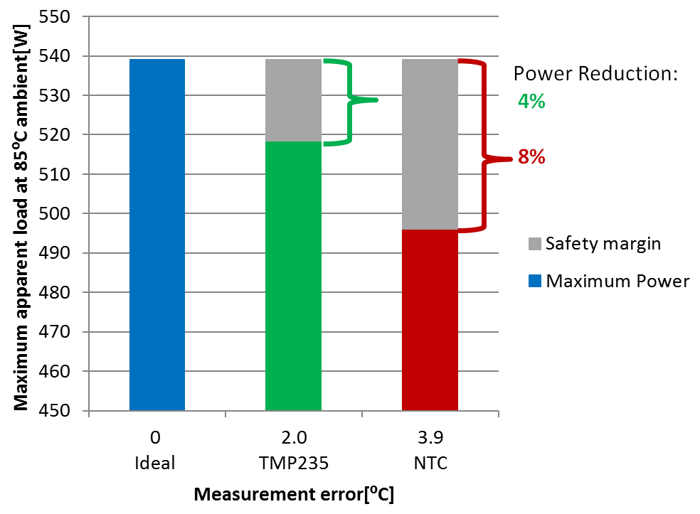
Part 1 identified that temperature sensor error introduces a safety margin that affects the safe operating area of the power stage. Aside from sensor error, another error not accounted for in the comparison shown in Figure 1 is the analog-to-digital converter (ADC) error, since both the TMP235A2 and negative temperature coefficient thermistor (NTC) are delivering an analog signal. The ADC error will effect both signals equally, however at hotter temperatures NTCs become very nonlinear which adds to the challenge of obtaining an accurate measurement. A silicon temperature sensor like the TMP235 maintains its linearity across temperature, making it easier to compensate the error. Also, an emerging product, like the TMP61 linear thermistor offers similar linearity as that of silicon temperature sensor, but footprint compatible with surface mount NTCs, making it easy to compensate for errors and replace NTCs.
 Figure 1 Usable apparent load at 85°C
using different temperature sensors
Figure 1 Usable apparent load at 85°C
using different temperature sensorsA digital temperature sensor like the TMP117 or TMP1826 can eliminate the ADC error and achieve an apparent load that’s much closer to the “ideal” curve achieved using a thermal camera. TMP1826 only requires two wires (i.e. data and ground) that offers RTD rated accuracy without additional signal chain circuitries and system errors.
When your system is operating at an ambient temperature of 85°C, the printed circuit board (PCB) and integrated circuits (ICs) are in fact working at a higher temperature due to the self-heating of the ICs. A typical industrial-grade IC has an operating temperature of 125°C or higher.
When the ambient temperature is 85°C, the self-heating of the ICs can only raise the IC up to 40°C. If the IC gets to a higher temperature the IC is working outside of temperature range. For more details about self-heating, see the 48-V, 500-W Three-Phase Inverter with Smart Gate Driver Reference Design for Servo Drives design guide.
To avoid working outside recommended temperature range, you need to ensure that your system does not exceed temperatures higher than 125°C. In the smart gate driver reference design, a thermal camera measures the temperature. In a real system, either a thermistor or IC sensor would measure this temperature. In the comparison shown in Figure 1, a small error is introduced into the calculations by incorrectly assuming that the thermal camera has no error and is ideal. A resistance temperature detector probe would offer a more accurate baseline method of sensing.
The various methods of the various sensor types add a measurement error, which needs to be compensated from the ideal measurement. The smaller the error, the more power the three-phase inverter can supply before the system must turn off due to an over temperature error. In other words, the temperature sensor will limit your overall system’s apparent load capabilities without even looking at the gate driver, field effect transistors or any of the other factors affecting power-stage efficiency. This is why temperature sensor accuracy is so important.
What does this mean for your design? Let’s use the smart gate driver reference design as an example and compare the temperature error of an NTC thermistor with the TMP235A2 IC temperature sensor. First, how do you quantify the temperature error?
Looking at the TMP235A2’s data sheet, it has a temperature error of ±2°C for the full temperature range. There is a small footnote in the data sheet that refers to the lookup table used to correct the device for temperature drift.
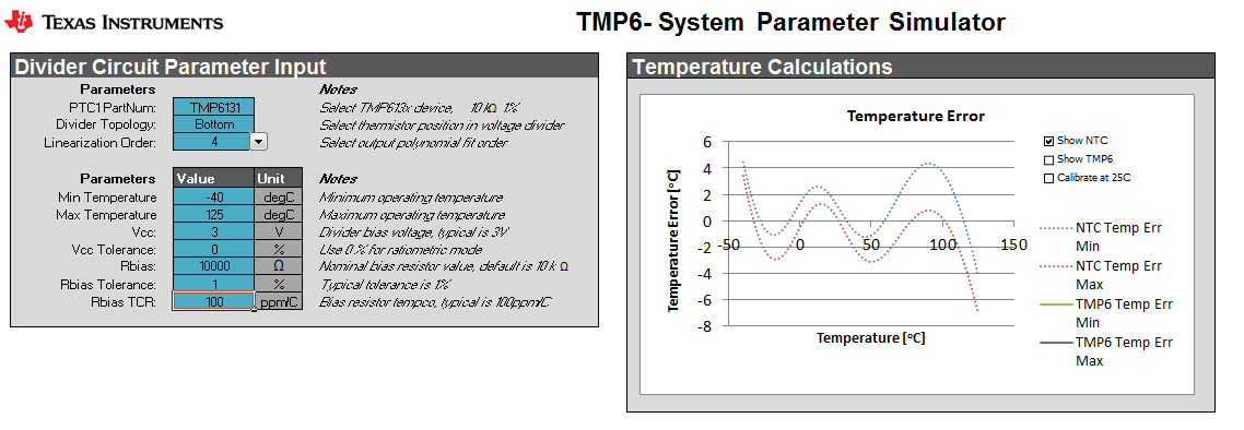
For the NTC, it takes a little more time to calculate the error. Mathematical equations can generate a model that you can use to calculate the error in Celsius degrees. The equations can typically be found on the NTC data sheet or NTC application notes. With these equations, you can generate the curves representing the NTC model, as seen in the TMP6131 parameter simulator.
The TMP6131 system parameter simulator can simulate the NTC model and estimate the accuracy when applying polynomial fitting, as opposed to a lookup table. Figure 2 shows the setting used for the simulation and the result.
 Figure 2 Temperature error calculation
of an NTC using the TMP6131 system parameter simulator
Figure 2 Temperature error calculation
of an NTC using the TMP6131 system parameter simulatorThe blue curve in Figure 2 defines the temperature error. The area used is from -40°C to +125°C. You can see that the maximum negative and positive error is –3.6°C and +4.3°C, respectively. For ease of calculation let’s normalize this temperature error range to ±3.9°C of the NTC. Due to the NTC’s nonlinearity over temperature, the compensation should occur in the temperature range specified for the system.
There are two basic ways to linearize thermistors in software: polynomial fitting and a lookup table. These methods will get the NTC, PTC and or TMP235A2 measurements closer to the ideal measurement and actual temperature. In the simulation tool, polynomial fitting will reduce the linearization error. Using a higher polynomial fitting order increases the NTC’s accuracy, but also increases the time it takes for the processor to calculate the temperature. This extra calculation time results in additional power consumption, which also affects system efficiency. The lookup tables require processor memory.
Calibration errors are not considered in the simulation, but will affect both the sensors similarly.
Conclusion
Additional resources
- Check out the TMP6131 system parameter calculator.
- Read the application report, Methods to Reduce Thermistor Linearization Error, Memory and Power Requirements Over Wide Operating Temperature Ranges.
- Get more information on TI precision temperature sensors.