SSZT573 december   2018 ADS131A04 , AMC1301 , OPA4180


  1.   1
  2.   2
    1.     3
    2.     Grid Protection and Measurement
    3.     Protection and Measurement Class Accuracy Requirements for Current, Voltage and Active Energy
    4.     Current Transformers
    5.     Potential Transformers
    6.     Power and Energy
    7.     Design Performance Summary

Kallikuppa Sreenivasa

In my two previous blog posts on improving data acquisition (DAQ) for grid protection and control, I discussed the need for interfacing multiple analog-to-digital converters (ADCs) to a single processor and using the programmable real-time unit subsystem and industrial communication subsystem (PRU-ICSS) to improve sensor DAQ performance. In this post, I will discuss the DAQ accuracy requirements for voltage, current and active energy used in grid applications and discuss our High Accuracy ±0.5% Current and Isolated Voltage Measurement Reference Design Using 24-Bit Delta-Sigma ADC, which is based on the ADS131A04 24-bit delta-sigma ADC.

Moving from conventional to intelligent substations
GUID-9969BED6-64A6-48AA-9BA0-6A3793C3B56D-low.png Learn more about intelligent substations by reading our new white paper, "Moving from conventional to intelligent substations."

Grid Protection and Measurement

DAQ is used for protection of grid assets and measurement of electrical parameters for metering/monitoring. Measuring a wide range of voltage and current inputs (covering protection and measurement-range) within a specified accuracy limit using a single hardware configuration is a key requirement.

To protect grid primary equipment, the DAQ (secondary equipment) must measure voltage and current inputs accurately over a wide input range in order to provide repeatable fault detection and trip-time performance. For protection, an accuracy class specifies the voltage (3P) and current (5P, 10P) range, depending on the grid primary equipment. For measurement, the current range is 5% of the rated current In to the maximum current, which is four times In (1 A or 5 A); the voltage range is specified from 80%-120% of the rated voltage Vn. A DAQ used in grid applications additionally provides energy measurement functions with an accuracy class 1 or better for a limited range. An analog front end (AFE), which measures a wide range of inputs accurately meeting both protection and measurement class accuracy requirements, simplifies DAQ design.

The AFE shown in Figure 1 includes a sensor interface, gain scaling to the ADC range, input transient protection, analog-to-digital conversion and a host interface.
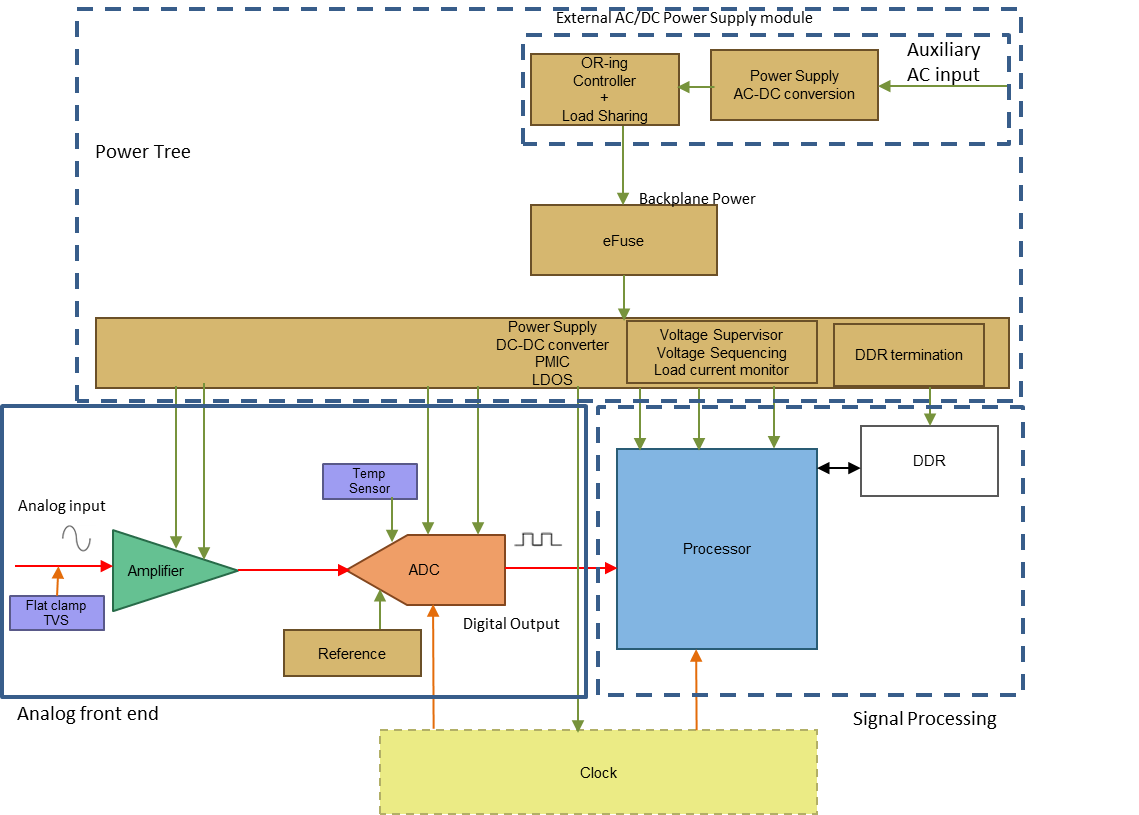
GUID-8D90711A-D4F0-43FF-BB67-CD9DB1FE318D-low.png Figure 1 DAQ Subsystems Including an AFE

Protection and Measurement Class Accuracy Requirements for Current, Voltage and Active Energy

A current transformer (CT) transforms primary current to a proportional secondary current and a potential transformer (PT) transforms primary voltage to a proportional secondary voltage. The measurement range and accuracy requirements for current, voltage and active energy varies with specified accuracy class and the below section provides more details

Current Transformers

CTs are used to protect equipment against overload, short-circuit and unbalance. The accuracy of protection-class CTs is low, but still high enough to sense fault currents. In protection-class CTs, the error is specified at 100% of In. Protection class CTs are specified as 5P20, meaning that at 20 times In (accuracy limit factor) the error must be <±5%. Standard accuracy-limit factors are 5, 10, 20 and 30 and P indicates protection class. Measurement class CTs has higher accuracy requirements with a limited range.
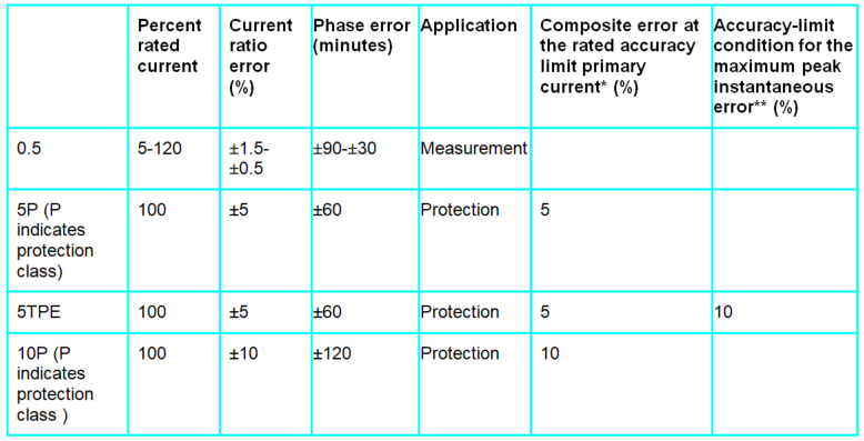
More grid equipment now uses non-conventional instrument transformers including an electronic current transformer (ECT). ECTs are characterized by small volume, light weight, increased isolation, good linearity and easy digitization. ECT specifies a special class of accuracy limits called transient protection electronic (TPE) class. Class TPE is defined by a maximum peak instantaneous error of 10% at the accuracy-limit condition. A Class 5 TPE ECT meets the requirements for protection applications and fault transient recording. Table 1 lists the accuracy requirements for measurement and protection class.

Table 1 Measurement and Protection-class CT Accuracy Requirements, Including Transient
GUID-81E24064-28F8-45FC-9873-BD628C045B16-low.png

*The rated accuracy limit primary current is the value of the primary current up to which the protection-class CT complies with composite error accuracy requirements.

**The peak instantaneous error assesses the error of transient DC and AC components.

Potential Transformers

PTs are used for protection equipment against voltage failure/unbalance. PTs transform the primary voltage to a rated voltage Vn of 110 V/240 V on the secondary side. The primary voltage depends on the application. Table 2 lists the accuracy requirements for measurement and protection class.

Table 2 Measurement and Protection-class PT Accuracy Requirements
GUID-8ED020A2-4E34-47F7-BFA3-52DF53A5D916-low.png

Power and Energy

In addition to measuring voltage and current within the specified accuracy range, DAQ in grid applications also measures power and energy for implementing specialized protections and monitoring. Table 3 lists the accuracy requirements.

Table 3 Accuracy Limits for Accuracy Class 1 Active Energy
GUID-7A3C018A-32DE-4899-95DC-FC32C3430F8C-low.png

Our reference design for current and isolated voltage measurement shows how to measure voltage, current and energy with high accuracy over a wide input range and has the functional blocks as shown in Figure 2.
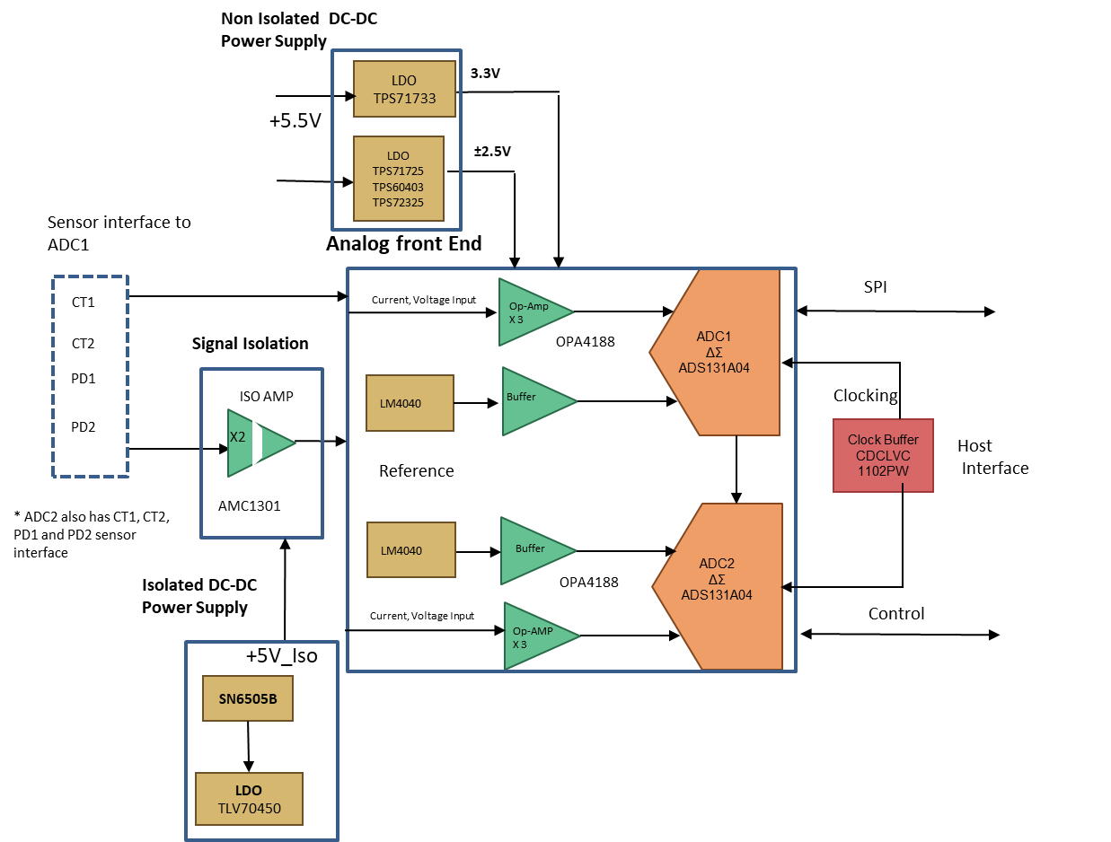
GUID-E52DD9FF-65B7-4EEF-B3C0-4AC174D024D3-low.png Figure 2 Reference Design AFE Block Diagram

The key functions of the AFE are:

  • Isolated voltage input: An onboard resistor divider scales input voltages to 0-175 mV rms for measurement using the AMC1301 isolation amplifier with ±250-mV input and a differential output with 8.2 gain.
  • Isolated power: A transformer driver and low-dropout regulator generate the required isolated supply.
  • Non-isolated voltage input: An onboard resistor divider scales input voltages to 0-1,000 mV rms for measurement along with a gain amplifier.
  • Current input: You can connect an external CT to an onboard burden resistor with gain amplifiers to measure the current inputs.
  • Gain amplifier: A scalable fixed-gain operational amplifier scales the inputs to the ADC range.
  • ADC and host interface: The output of the gain amplifiers are interfaced to the ADS131A04 24-bit delta-sigma four-channel simultaneous-sampling ADC, with an input range of ±2.5 V and a configurable reference of 2.44 V or 4 V depending on the signal input range. The ADC interfaces to the host using Serial Peripheral Interface.
  • Temperature sensor: to compensate for temperature-related accuracy drift.

In the reference design, two ADCs are chained and a common clock with clock buffer is used to synchronize all channels. Chaining of two ADCs together expanded the input channel to 8 with a synchronization delay of 5-µs or less between channels.

Design Performance Summary

I tested the design performance using a CT/Rogowski coil with a fixed-gain amplifier for current measurement and potential divider with a fixed-gain amplifier/isolation amplifier for voltage measurements. The measurement accuracy is within ±0.5% for different integration periods ranging from 100ms to 1000ms. The dynamic range performance for current inputs was >500 to 1 (the ratio between maximum and minimum current measured), which meets both measurement and protection class accuracy requirements with standard accuracy limit factors ≥30. The AFE can be used with a low-power CT with a 0.6-mV to 333-mV input per International Electrotechnical Commission (IEC) 60044-8.

In my next post, my colleague Akshay Mehta and I will discuss power architecture options for improving DAQ performance.