SSZT587 november 2018 LM73605
Is enable hysteresis not included in the DC/DC converter you are designing with? Or is the built-in enable hysteresis too small?
Modern DC/DC converters use an enable pin to control the design conditions at which the power supply turns on and off. It is possible, however, to add an adjustable hysteresis to your DC/DC converter’s enable signal. You can replicate this technique using Excel spreadsheet calculations, Texas Instruments (TI) TINA-TI™ software simulations and evaluation module (EVM) testing.
It is standard electrical engineering practice to add a hysteresis resistor around a comparator (adding feedback). You can apply this same idea to a DC/DC converter by adding a resistor connecting the enable signal to the output voltage. By adding the output voltage to the enable signal, the enable signal will be pulled even higher once the converter produces an output. Figure 1 shows a simplified schematic.
 Figure 1 Simplified DC/DC Converter
Schematic
Figure 1 Simplified DC/DC Converter
SchematicYou can use Equations 1 through 4 to calculate the correct resistor values based on the design parameters:

where RT is the top feedback resistor in the enable resistor network, RB is the bottom feedback resistor in the enable resistor network, VON is the desired input voltage for turnon, VOFF is the desired input voltage for turnoff, RHYS is the hysteresis resistor, IDRAW is the current drawn by the enable resistor network and VEN is the enable threshold voltage (a data-sheet specification).
Example
- VIN typical = 12V.
- VON = 10V.
- VOFF = 7.5V.
- VOUT = 5V.
- VEN = 1.2V (no internal hysteresis).
Now let’s look at the calculations, simulations and test data for this additional hysteresis.
Step 1: Use the Design Calculator to Determine Resistor Values
 |
The Excel calculator quickly recommends the appropriate component values for the desired VON and VOFF. Table 1 also shows the calculated RT, RB and RHYS values to meet the input criteria.
Step 2: Simulate the Values Using TINA-TI Software
 Figure 2 TINA-TI Simulation
Schematic
Figure 2 TINA-TI Simulation
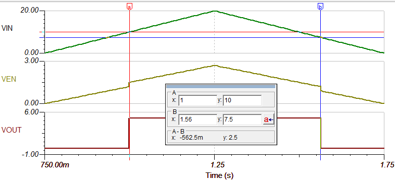
SchematicClick Analysis and then Transient Analysis to run the simulation. Running from 750ms to 1.75s will show a full turnon, turnoff cycle. Figure 3 shows the simulation results.
 Figure 3 TINA-TI Simulation Transient Results
Step 3: Validate on an EVM
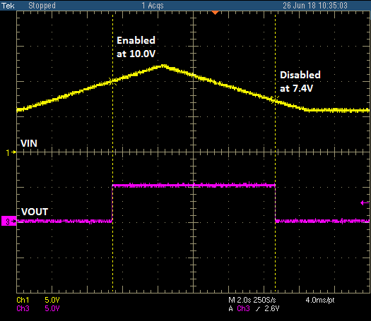
 Figure 4 EVM Testing Results