SSZT639 August 2018 DRV8828 , DRV8880 , DRV8881 , DRV8886AT
When I first heard about stepper motor tuning, I was really confused. How can a motor be out of tune? I started reminiscing about warming up for band concerts in high school and wondered how system designers could do something similar for their motors.
After watching a video from my colleague Matt Hein I learned these three things about stepper motor tuning:
- Stepper motor tuning relates to how well the current regulation scheme maintains current in a stepper motor’s coils. Poor tuning occurs when the stepper driver does not properly regulate the current in the coils to the appropriate level. A poorly tuned stepper motor will have a jerky motion and significant vibration. Poor tuning can also negatively impact the efficiency of the motor drive system.
- Tuning the stepper motor can be time-consuming because finding the optimal fixed decay settings for a given motor, voltage, current and speed is a trial-and-error process.
-
Stepper motor tuning is especially important for microstepping. Microstepping gives stepper motors fine positional control. The current waveform of a tuned stepper motor should approximate a sine wave, as shown in Figure 1.
 Figure 1 Stepper Motor Coil Current
for a 25V Supply, 2,500 Pulses per Second (PPS) and One-eighth Microstepping
Using Ripple Control on the TI DRV8886AT
Figure 1 Stepper Motor Coil Current
for a 25V Supply, 2,500 Pulses per Second (PPS) and One-eighth Microstepping
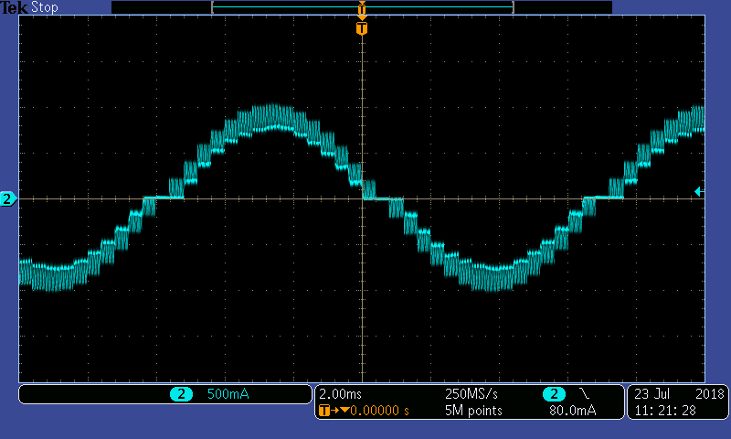
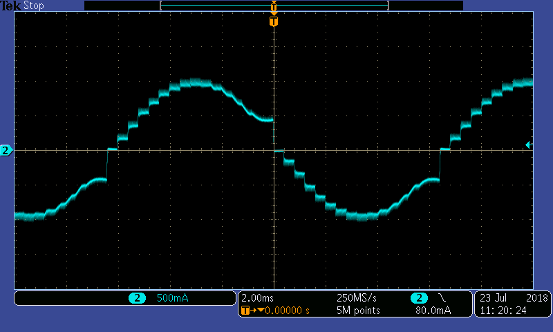
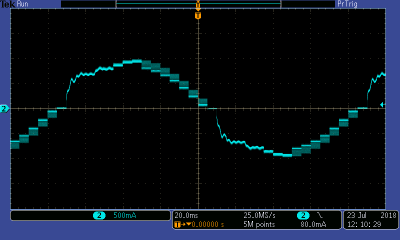
Using Ripple Control on the TI DRV8886ATHowever, engineers who work with stepper motors do not always see a waveform like Figure 1 the first time they connect their motor. They may see waveforms like the ones shown in Figure 2, Figure 3, or Figure 4. These figures are examples of poor stepper motor tuning, and will cause excessive vibration and noise from the stepper motor.
 Figure 2 Stepper Motor Waveform
with 60% Fast Decay
 Figure 3 Stepper Motor Waveform
with Slow Decay
 Figure 4 Stepper Motor Waveform at
a Slow Speed (200PPS) with Slow Decay/50% Mixed Decay
Figure 4 Stepper Motor Waveform at
a Slow Speed (200PPS) with Slow Decay/50% Mixed DecayIn each of these cases, the decay setting chosen for the current regulation scheme (also called current chopping) was not appropriate for the chosen motor, supply voltage, full-scale current, and speed.
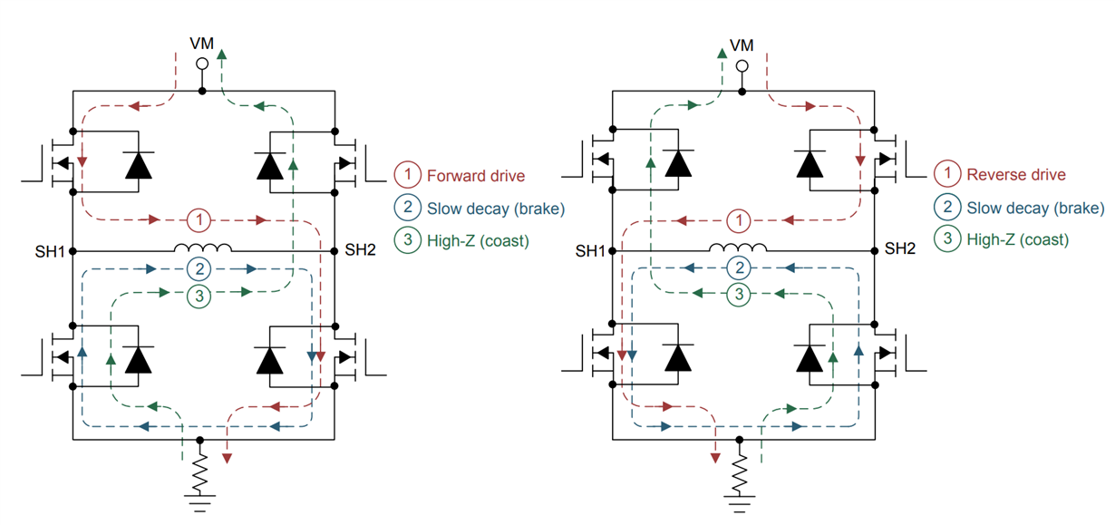
Stepper motor tuning is the process of choosing the proper decay setting during the off time of the PWM current chopping cycle (tOFF). Figure 5 shows the different ways that current can flow through the H-bridges of a stepper driver. During fast decay, the field-effect transistors (FETs) opposite from the driving FETs turn on, and the current flows from the motor back to the power supply. For this condition, the current decreases quickly. During slow decay, the two low-side FETs turn on, and the current recirculates through these FETs. For this condition, the current decays much more slowly.
 Figure 5 Current Paths through the
H-bridge During Normal Operation (Driving), Dead Time (All FETs Are off), Fast
Decay and Slow Decay
Figure 5 Current Paths through the
H-bridge During Normal Operation (Driving), Dead Time (All FETs Are off), Fast
Decay and Slow DecayDuring stepper motor tuning, engineers search for the optimal “mixed” decay setting for the stepper. Mixed decay consists of a combination of fast and slow decay when the driver is not driving current into the coils. Choosing the mixed-decay settings means setting the percentage of fast decay versus slow decay for the off time.
Figure 6 shows how mixed decay helps regulate the current.
 Figure 6 Using Mixed Decay to Regulate
the Current at Each Microstep Level
Figure 6 Using Mixed Decay to Regulate
the Current at Each Microstep LevelSome customers have told us that it can take as long as a month to find the proper decay settings for their stepper motor. The combination of the supply voltage, back electromotive force (EMF) and microstepping current levels all impact the way the current in the stepper coils charges and discharges.
The following list provides some details as to why this is the case:
- Back EMF will change with speed and load torque. Back EMF opposes the supply voltage, so the effective voltage across the coil is smaller.
- The application may require the stepper motor to operate at a wide range of speeds.
- Each current level required for microstepping has a different ITRIP threshold, which will impact the timing of the current charging and discharging in the coil. Because of this, choosing a fixed mixed-decay setting is difficult because it has to regulate the current under all of those conditions.
Table 1 provides explanations for why the decay modes chosen in Figure 2, Figure 3, and Figure 4 exhibit poor tuning.
| Conditions | Tuning issue | |
|---|---|---|
| Figure 2 | 25V supply, 2,500PPS, 1/8 microstepping, 60% fast decay for increasing and decreasing current | Too much fast decay percentage causes large ripple currents |
| Figure 3 | 25V supply, 2,500PPS, 1/8 microstepping, slow decay for increasing and decreasing current | Significant back EMF distorts the waveform when the current decreases using slow decay |
| Figure 4 | 25V supply, 200PPS, 1/8 microstepping, slow decay for increasing current and 50% fast decay for decreasing current | The blanking time for slow decay is too long, so the motor coils charge faster than the driver can regulate the current |
At this point, you may be thinking, “Instead of manually testing all of the fixed mixed-decay settings to find the best one, what if the stepper driver had some kind of smart tuning feature to choose the best mixed-decay setting while driving the motor in real time?”
Devices like the DRV8880, DRV8881 and DRV8886AT have smart tuning features that can help eliminate the time-consuming effort of stepper motor tuning. All of these devices have the option to select dynamic decay, which is a smart tuning feature that automatically adjusts the percentage of fast decay used in the total off time. The DRV8886AT has an additional smart tuning feature called ripple control that regulates the current at each microstep level between the upper and lower thresholds. Ripple control only uses slow decay, but because the driver continually senses and adjusts the current, the current does not lose regulation.
Other than achieving nice sinusoidal current waveforms like Figure 1, these smart tuning features have other benefits as well. When the stepper motor has a well-tuned current waveform, it runs more quietly and more efficiently. Interestingly, the examples of poor tuning in Figure 2, Figure 3, and Figure 4 all result in currents larger than the targeted stepper motor current at certain microstep levels. This excess current increases the temperature of the motor and the driver. With dynamic decay and ripple control, the driver does not use excess current at each microstep level. Figure 7 shows how a stepper motor tuned with dynamic decay reduces thermal dissipation of the stepper driver chip.
 Figure 7 Dynamic Decay vs. Mixed Decay
at Various TOFF Times
Figure 7 Dynamic Decay vs. Mixed Decay
at Various TOFF TimesUltimately, smart tuning features like dynamic decay and ripple control can help you save time and reduce temperature and noise in your stepper motor applications.
Additional Resources
- For more information on dynamic decay and ripple control, check out the data sheets for the DRV8880, DRV8881, and DRV8886AT
- The application report Current Recirculation and Decay Modes explains the decay modes used in stepper driving in greater detail