SSZT807 february 2018 TPS543B20 , TPS543C20
In a perfect world, a power supply provides an ideal voltage and never varies, but in reality,, all power supplies have some error associated with the output voltage accuracy at steady state. This can cause serious problems in some applications, occasionally causing logic errors, shutdown or lasting damage. In this post, I take a look at a feature used in fixed-frequency DC/DC buck converters that can help improve transient response during a load current increase, and why devices that use this feature are worth considering for Arria 10 and Stratix 10 FPGA applications.
Undershoot and Overshoot Explained
As previously mentioned, the output voltage accuracy of power supplies isn't perfect. When the load current increases or decreases, the power supply’s output voltage can deviate from the nominal voltage, causing undershoot and overshoot. Undershoot is when the output voltage drops below the nominal voltage and overshoot is when the output voltage rises above the nominal voltage. If a power supply’s output voltage deviates in excess of a powered device’s input specification, unwanted behavior could result. Excessive undershoot can deprive the powered device of its minimum operating voltage and cause logic errors or shut-down while excessive overshoot can stress and damage sensitive devices.
Introducing API
For fixed-frequency DC/DC converters, during a sudden rise in load current there is a corresponding drop in output voltage. In order to limit the amount of drop in output voltage, the on-time of the converter is increased, which increases the duty cycle. But the control loop can only increase the on-time either during an unfinished on-time or it must wait until the next switching cycle. So for a fixed-frequency DC/DC converter, if a load transient occurs in the middle of a switching cycle during the off-time, the converter will not react until the next switching cycle. As a worst-case scenario, assume that the transient occurs at the start of this off-time. Consider Equation 1 where I calculate the off-time, or potential wait time (not taking forced dead time into account):
As I mentioned, one of the contributing factors to transient response is the amount of time it takes for the converter to react. So how can you shorten the reaction time, considering the worst-case scenario? Increasing the switching frequency is one option, but has its own drawbacks, such as lower efficiency. Increasing the duty cycle (VOUT/VIN) might not always be feasible since these values are likely predetermined. This is where API comes in… literally.
How API Works to Minimize Transient Response Time and Undershoot
| Min | Typ | Max | Unit |
|---|---|---|---|
| 1.71 | 1.80 | 1.89 | V |
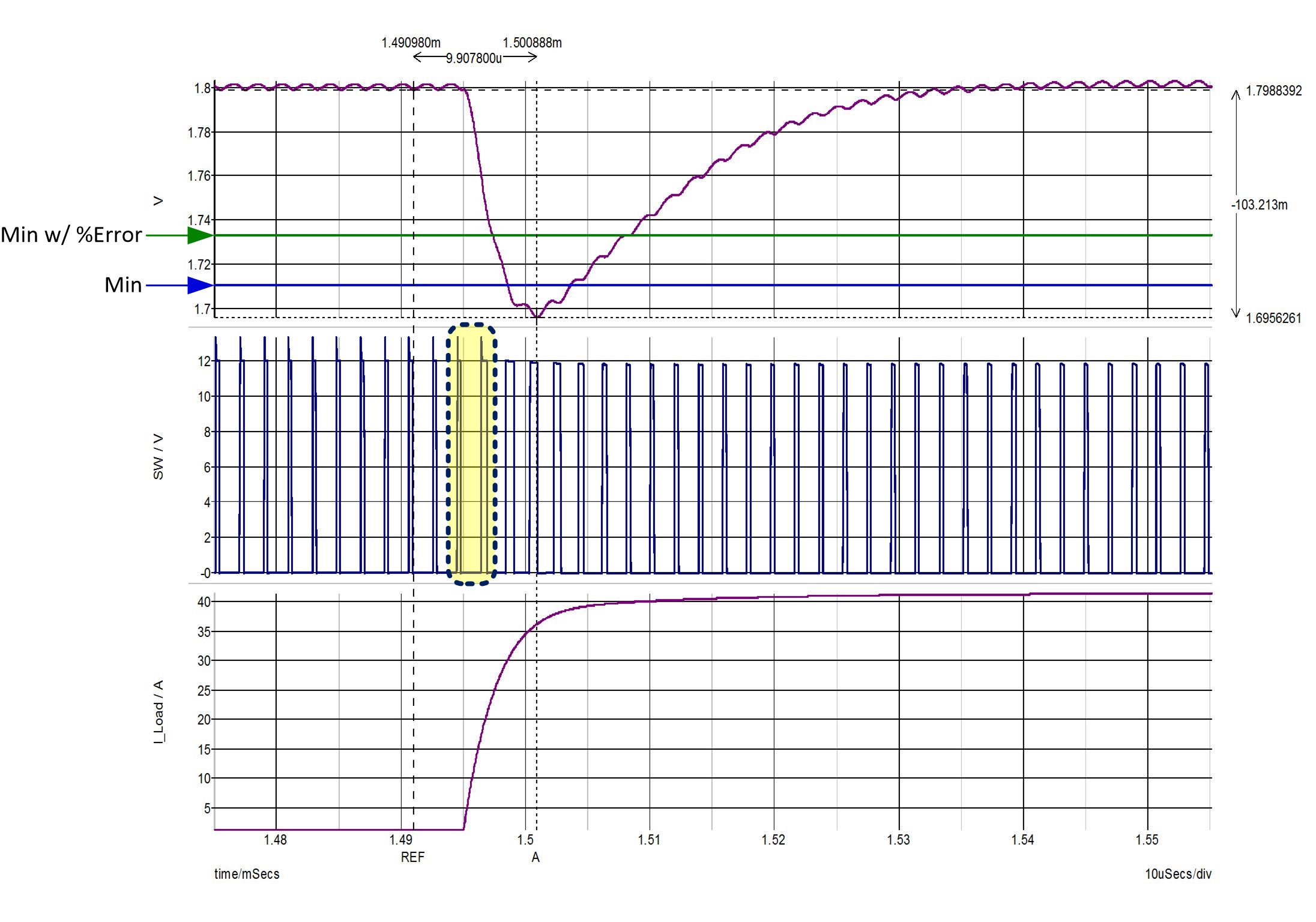
Figure 1 shows a load transient simulation of a fixed-frequency converter without API. The upper waveform in Figure 1 is the output voltage, which falls below the required minimum operating voltage labelled “Min” at 1.71V.
In addition to the required maximum and minimum values for this particular rail, there is a percentage of error associated with the actual output voltage of the power supply when compared to the target voltage. If we consider the output voltage deviation based on feedback resistors with a 1% tolerance, and a reference voltage with 0.5% accuracy, the resulting output voltage accuracy error percentage is approximately ±1.27%. This decreases the amount of available tolerance by ±23mV, which is also shown in Figure 1 labelled “Min w/ %Error” at 1.733V.
The middle waveform in Figure 1 is the switch node; here you can see that the load current (the lower waveform in Figure 1) begins to ramp up in between the two highlighted on-times. Now let’s look at the same simulation, only this time with API enabled.
 Figure 1 A Load Transient Simulation of
a Fixed-frequency Converter without API
Figure 1 A Load Transient Simulation of
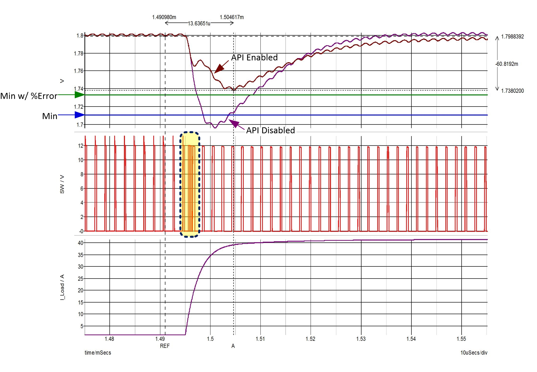
a Fixed-frequency Converter without APIFigure 2 shows a load transient simulation of a fixed-frequency converter with API enabled. The upper waveform in Figure 2 is the output voltage, which now remains within the operating range of the expected voltage values listed in Table 1 labeled “Min”, as well as the minimum taking output voltage accuracy into account labeled “Min w/ %Error” at 1.733V. The middle waveform in Figure 2 is the switch node; here you can see that the load current (the lower waveform in Figure 2) ramps up at the same point in respect to the switching cycle compared to the previous simulation. Only now you can see that there are additional on-times caused by the injected pulse-width modulation (PWM) pulse.
 Figure 2 A Load Transient Simulation of
a Fixed-frequency Converter with API, with the Switch Node Highlighted
Figure 2 A Load Transient Simulation of
a Fixed-frequency Converter with API, with the Switch Node HighlightedThere is over 40mV of undershoot reduction in the simulation that used API for this particular model. During the load transient, the API pulses increased the duty cycle and switching frequency and reduced the delay between the occurrence of the event and the modulator’s reaction. The amount of pulses and sensitivity will depend on the specific converter with this feature and your design choices. After injecting the API pulse(s), the converter increases the on-time over a fixed frequency in order to bring the output voltage back to the target value as it normally would. One consideration when using API is that if one or more pulses are injected during a load transient, the switching frequency will vary temporarily.
Undershoot in a Device with and without API Enabled
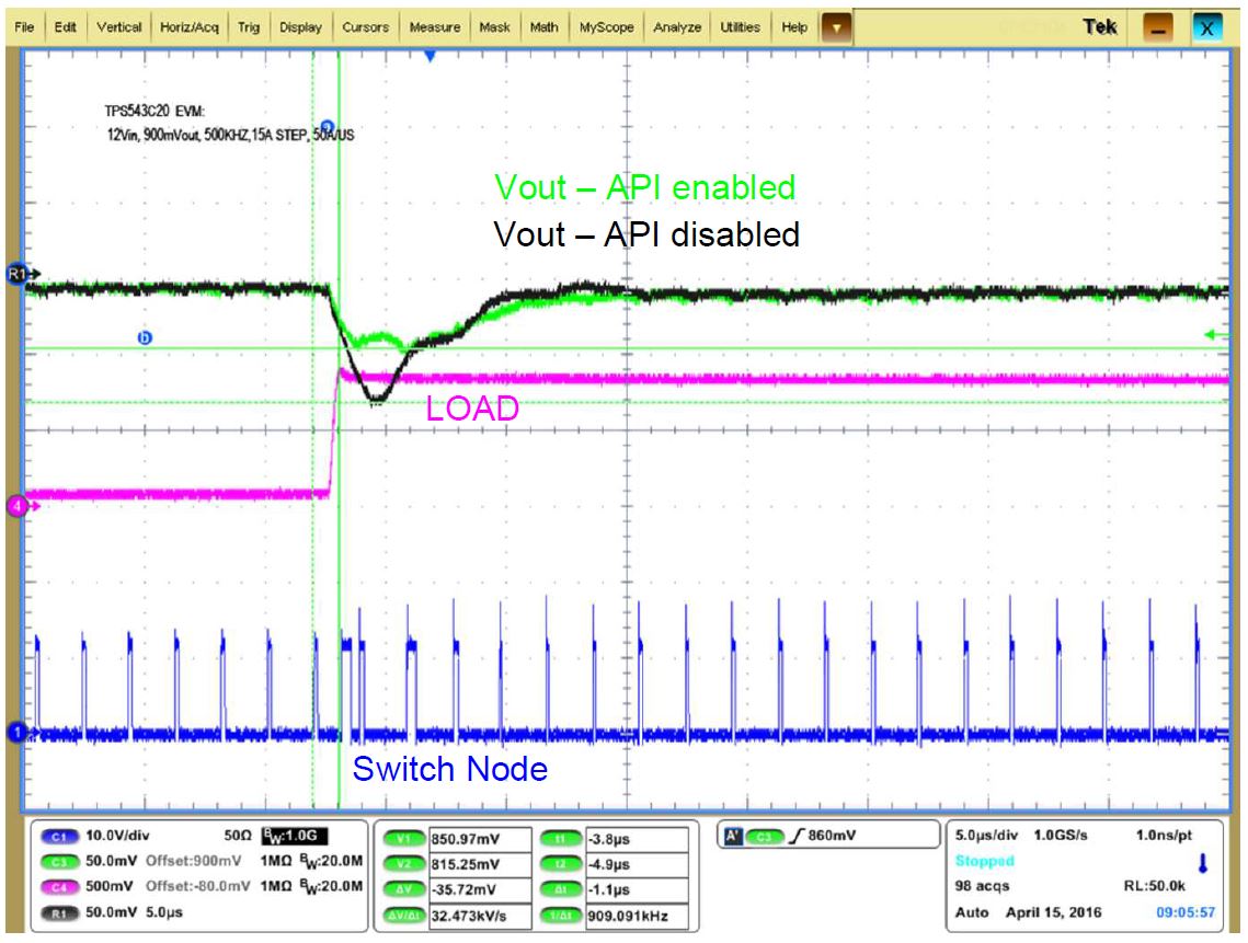
Figure 3 shows the difference with and without API based on actual bench results of the TPS543C20, a 40A device that’s capable of 80A when stacked. The test configuration was a 12V input voltage, 0.9V output voltage, 500kHz switching frequency and 15A step up/step down with a slew rate of 50A/µs. When comparing the same device with and without these features enabled, undershoot was approximately 36mV less with API enabled.
 Figure 3 Undershoot with API
Enabled/disabled
Figure 3 Undershoot with API
Enabled/disabledAs shown in the simulation and bench testing enabling API resulted in less deviation from the nominal output voltage during load transients, and improved the converter’s response time, when compared to API being disabled. This feature offered in the TPS543B20 and TPS543C20 devices that can reduce the amount of undershoot during a load current increase with the same amount of output capacitance, which is something to consider when designing in Arria 10 and Stratix 10 FPGAs.
Conclusion
You might be wondering, what about the overshoot caused by a load current decrease? These same devices offer a feature to improve transient response during a load current decrease as well. I will be taking a look at it in my next blog: Improving overshoot of voltage regulators for Intel Arria 10 and Stratix 10 FPGAs.
Additional Resources
- Get more information on powering the Arria 10 and Stratix 10 FPGAs.
- Estimate actual load current and transient specifications for Altera devices with the Early Power Estimator (EPE) and Power Delivery Network (PDN).
- Learn more about TI power management for Altera FPGAs.