SSZT820 january 2018 TPS62097-Q1
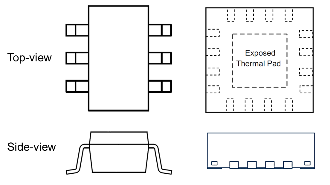
Designing an automotive application is an extremely complex task that involves several functional areas, which can make the decision-making process difficult when you have conflicting priorities. Package type is one example that has a huge impact on multiple aspects of your design: on the one hand, you have to ensure the device’s electrical and thermal performance; on the other hand, you will have concerns about manufacturability, quality control and reliability. When deciding on your power-management integrated circuits (ICs), you may have to choose between leaded small-outline transistor (SOT) packages and unleaded quad flat no-lead (QFN) packages. Figure 1 shows an example of each package type.
 Figure 1 Package Drawings for SOT
(Left) and QFN (Right)
Figure 1 Package Drawings for SOT
(Left) and QFN (Right)SOT packages are simple and easy to use and inspect during manufacturing, thanks to the leads jutting out from the side of the package (more precisely, the mold compound). The additional length of the leads comes at some cost – in electrical performance (increased lead inductance), worsened thermal performance (no exposed thermal pad) and larger solution size.
QFN packages offer smaller size, reduced lead inductance and an exposed thermal pad for improved heat dissipation. Electrical and thermal performance are better than leaded packages, so on this basis alone, QFN would be the best choice.
One challenge for QFN, however, is the inspection of the soldering process during manufacturing. Insufficiently soldered devices result in reduced board-level reliability: if the mechanical link between a device and printed circuit board (PCB) is weak, the link may fail when the PCB is exposed to an abrupt temperature change or subjected to mechanical stress. To avoid this reliability risk and control soldering quality, you need an inspection process in place.
SOT packages are very easy to inspect with an automatic optical inspection (AOI) system because the leads and solder are clearly visible. For QFN packages, setting up an AOI system is trickier, as the leads are located underneath the package mold compound. To make AOI on QFN packages possible, the solder needs to form side fillets after soldering; otherwise, the AOI system cannot see whether the package is correctly soldered or not. Ensuring that this occurs reliably in a production environment is challenging, which can mean a more expensive X-ray inspection process and increased manufacturing time and costs. Figure 2 shows examples of observed solder wetting with QFN packages: an AOI system would have trouble distinguishing between poor soldering and good soldering in the event of limited side wetting.
 Figure 2 QFN Package Soldering with Limited Side Wetting and Poor Soldering on One Lead (Left); Limited Side Wetting and Good Soldering (Center); Full Side Wetting and Good Soldering (Right)
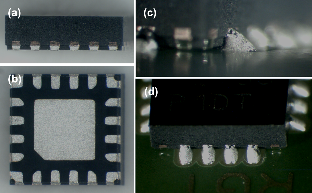
Adding wettable flanks to help improve side wetting after soldering makes QFN packages easier to inspect with AOI. A wettable flank has a step-cut lead frame and tin (Sn) added on the sidewalls via a replating process. This process allows the side fillet to form more reliably and makes it more visible and easily identifiable with AOI, as shown in Figure 3.
 Figure 3 Side (a) and Bottom (b) View
of a QFN Package with Wettable Flanks; Side (c) and Top (d) Views of QFN Package
Soldering with Wettable Flanks
Figure 3 Side (a) and Bottom (b) View
of a QFN Package with Wettable Flanks; Side (c) and Top (d) Views of QFN Package
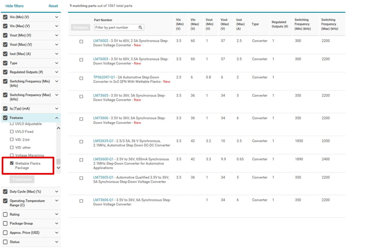
Soldering with Wettable FlanksTI offers a range of Automotive Electronics Council Q100-qualified step-down DC/DC converters in QFN packaging with wettable flanks to help you take advantage of the electrical and thermal benefits that QFN packages offer in your automotive designs. Figure 4 shows how you can find these devices on TI’s website by using parametric search and selecting Wettable Flanks Package in the Features tab.
 Figure 4 Filtering Step-down DC/DC Products for Wettable Flanks on TI.com
For example, the TPS62097-Q1 is TI’s first 6V step-down converter in a 3mm-by-3mm QFN package with wettable flanks. Thanks to our wider portfolio, we’re making it easier for you to use QFN packages in your design, and you can expect to see more product releases with wettable flanks for automotive applications in the future.
Additional Resources
- Watch the TI Training video, “Advanced Auto Packaging,” which discusses QFN slotted lead changes.
- Murray Roose explains “The value of wettable flank-plated QFN packaging for automotive applications” in this E2E™ Community blog post.
- Check out the application report, “QFN/SON PCB Attachment.”
- Watch a YouTube video about “Automotive HotRod™ and Wettable Flanks Packaging Advancements.”