SSZT869 november 2017 AWR1243 , AWR1443 , AWR1642
As the advanced driver assistance systems (ADAS) that drivers want increasingly rely on automotive radar sensors for more accurate sensing needs, the power consumption and heat dissipation of these sensors becomes an extremely important consideration. Heat dissipation has a direct bearing on the cost of the heat sink and housing needed by the sensor, as well as the radio frequency (RF) performance. Typically, the lower the power dissipation, the less need there is for expensive housing. The better the RF performance (indicated through numbers like noise figure and phase noise), the better the detection of objects at a farther range.
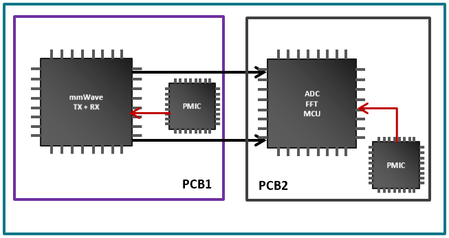
Existing radar solutions predominantly feature two chips: The RF transmitter and receiver chip on one printed circuit board (PCB) and the microcontroller (MCU) on other PCB, to perform the baseband processing. Some designs require a power-management solution for each of the PCBs as well, increasing solution size and design complexity. Figure 1 shows the components of a typical two chip mmWave sensing solution.

 Figure 1 Conventional Two-Chip Sensor
Solution
Figure 1 Conventional Two-Chip Sensor
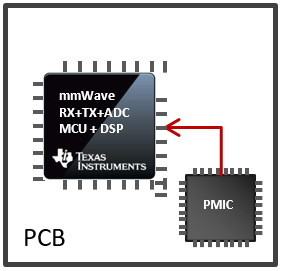
SolutionTo address the needs of automotive developers, Texas Instruments integrates all of these components into a single chip on a single PCB with a single power-management solution, show in Figure 2. The resulting sensor is much smaller and simpler to design with, making it more cost-effective to integrate into automotive designs.
The high level of analog and digital integration brings about one more important benefit: enhanced power dissipation. AWR1x single-chip devices dissipate the lowest amount of power and heat in the industry today. This is possible because the complementary metal-oxide semiconductor (CMOS) technology requires a lower supply voltage, has a smaller threshold voltage, and the digital circuits are >1 order of magnitude lower power due to the smaller capacitance and voltage.
 Figure 2 Texas Instruments Single-chip
Sensor With Integrated DSP
Figure 2 Texas Instruments Single-chip
Sensor With Integrated DSPThe parameter affecting power consumption and heat dissipation is the duty cycle at which a sensor operates. The definition of a duty cycle in simple terms is the ratio of time during which the sensor transmits a signal to the total frame time; for example, a 50% duty cycle would indicate a ratio of 10ms transmit time to a 20ms total time (the sensor transmits for 10ms and processes the reflected signal for the next 10ms, the total time being 20ms).
TI’s single-chip AWR1x sensors operating at a 25% duty cycle consumes less than 1.35W of power. This includes two transmitters and four receivers operating simultaneously, with the digital signal processor (DSP) sending detected object data over the Controller Area Network (CAN) interface. It’s possible to increase the duty cycle to 50% to detect objects at much farther ranges, with power consumption remaining low at less than 2W.
Compare this to existing solutions in the market. A typical two-chip solution (RF plus MCU) consumes anywhere between 3.5W to 4.5W, even at a 20 to 30% duty cycle. Power consumption is even greater at higher duty cycles, and the solution requires expensive heat sinks and costlier housing, increasing the total costs. In other words, TI AWR1x mmWave sensors can operate at higher duty cycles and dissipate less power compared to a competing two-chip solution and see objects at longer ranges, making them more effective for ADAS applications.
Table 1 summarizes power consumption at a system level including RF, power management and MCU components between a TI single-chip CMOS solution and a competing two-chip solution.
| TI AWR1x Single Chip (watts) | TI AWR1x Single Chip (watts) | Competing Two-Chip Solution (watts) | Competing Two-Chip Solution (watts) | |
|---|---|---|---|---|
| Duty cycle (%) | 25 | 50 | 25 | 50 |
| RF and integrated MCU | 1.35 | 2 | 1.5 | 2.25 |
| External MCU | Not required | Not required | 1 | 1.5 |
| Power-management integrated circuit and peripherals (75% efficiency) | 0.45 | 0.65 | 0.83 | 1.25 |
| Total | 1.8 | 2.65 | 3.3 | 5 |
It is also important to consider the heat dissipation. Silicon germanium (SiGe) processes tend to have higher localized hot spots due to uneven spread of the power dissipation. This leads to a large peak-junction temperature for the same bulk temperature and thermal resistance. On the other hand, CMOS processes tend to have more uniform temperature spread and the hot spots are not as pronounced. The consequence is a lower peak-junction temperature for the same amount of heat dissipation. The thermal constraints on the systems are thus much easier.
With the smallest form factor and lowest power consumption and heat dissipation, TI’s AWR1x CMOS single-chip solution can help automakers and Tier-1 suppliers reduce their overall solution cost and increase ease of development.