SSZT911 october 2017 THVD1450 , THVD1550
There are many different types and flavors of certification testing for semiconductor devices: electromagnetic interference and compatibility, electrostatic discharge, transient pulse, vibration resistance, humidity and temperature stress – the list goes on and on. These certification tests are meant to be realistic and repeatable lab experiments that are representative of the application environment of the device under test. Some of these tests are stand-alone and some are parts of whole suites; either way, there are a plethora of them to pass before your device can get to market.
With all of this testing comes the same confusion, learning curves and questions from customers and semiconductor manufacturers alike. What part of the device is this testing? Which standard defines this testing? How is this test performed? Why is it applicable to my project? What determines pass versus fail criteria, and why is that criteria relevant? The answers to these questions provide important details for properly preparing and executing the test, as well as passing certification levels without wasting time and money modifying and building a new printed circuit board (PCB) and endlessly debugging in the lab.
In this post, I’ll be focusing on a specific type of testing called electrical fast transient (EFT). Transient pulse testing is a type of interference measurement common in certification standards for several different industries, including industrial and automotive. Transient pulse testing is meant to assess a device and/or system’s ability to withstand damage and maintain proper communication and operation through pulses of high voltage on power and/or communication buses.
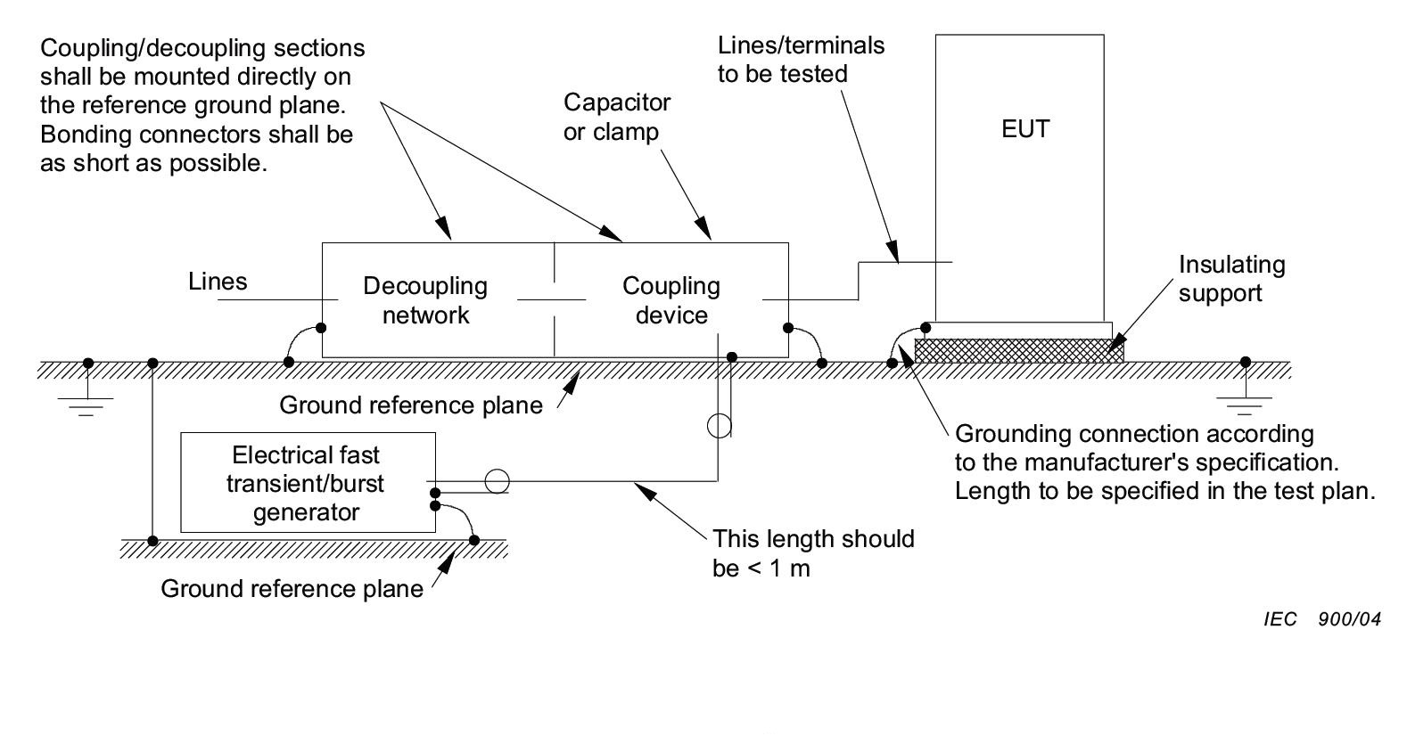
EFT is a form of transient pulse testing defined in the International Electrotechnical Commission (IEC) 61000-4-4 specification. Specific industries also derive their own EFT standards based on IEC 61000-4-4, like European standard 55024, which describes the requirements and criteria for information technology equipment in the European Union. EFT is a fast method relative to other transient pulse tests. There is a pulse waveform with a high peak voltage, fast rise time and high repetition rate that is meant to simulate the quick bursts of high-frequency energy caused by the switching of inductive loads like relay contactors or back-electromotive force from motors. These kinds of pulses are fairly common within industrial environments, so this kind of testing is crucial to guarantee that devices will maintain proper operation. Figure 1 shows a simplified circuit that would see the effects of EFT.
 Figure 1 Visual Representation of EFT
Pulses for Testing
Figure 1 Visual Representation of EFT
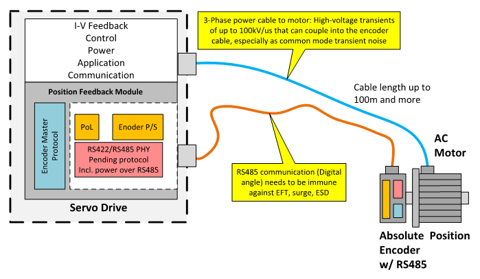
Pulses for TestingSome of our RS-485 transceivers have to undergo this type of testing. The RS-485 communication interface is used frequently in industrial settings for its inherent noise immunity and ability to work over long distances. In many systems that use RS-485, the devices are susceptible to fast transients because they are in contact with multiple pieces of an application. An example of this is in motor control, where the RS-485 transceiver is the interface between the motor encoder and the microcontroller. Since the transceiver is connected to the motor encoder, the transients don’t only couple in through the main AC and DC power shared with the motor; they also couple through communication and control signals. Having transients present along the communication waveforms is inevitable, but RS-485 devices must be immune to damage from these strikes, and also recover communication quickly enough so that any messages to or from the microcontroller aren’t interrupted or misinterpreted.
Here’s where TI’s new RS-485 transceivers, the THVD1550 and the THVD1450, come into play. Released this year, this device’s design emphasizes EFT and ESD protection, making it robust enough to thrive in the toughest industrial environments. TI created the High EMC Immunity RS-485 Interface Reference Design for Absolute Encoders specifically to showcase the immunity to EFT testing of the THVD1550. Figure 2 shows a typical absolute encoder circuit, and shows where EFT would affect this system.
 Figure 2 Absolute Encoder and Motor
Application Using RS485
Figure 2 Absolute Encoder and Motor
Application Using RS485Read part two of our What is an EFT blog series to learn how EFT testing is set up and executed, and why that is important to your product.
Additional Resources:
- Check out the High EMC Immunity RS-485 Interface Reference Design for Absolute Encoders
- Learn more about designing RS-485: Top 10 RS-485 Design Tips