SSZT990 august 2017 TPS62745
It is hard to choose a power topology for a wireless design when there are so many power-management integrated circuits (IC) out there. It may be hard to tell where to start, so I always start at the selection basics. The application of the design and onboard devices will determine the different voltage rails needed for operation.
Consider a smart lock or a heating, ventilation and air conditioning (HVAC) damper control system. This control system usually consists of a higher-voltage motor driver than the rest of the board The lower-voltage rail powers the MCU, radio and other sensing components.
A power management IC will make creating the different voltage rails easier. In the smart damper system, you have two ways to create two different voltage rails. The first option is to create the 3V rail with the batteries and then boost the voltage up to 6V for the motor driver. The second option is to have the batteries supply the 6V for the motor driver and then step the voltage down to 3V for the rest of the system.
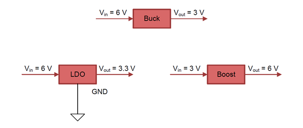
The next step in the design is to choose a power topology. Three main power topologies are possible for smart damper applications: low dropout (LDO) regulator, step-down converter (also known as buck) and boost (see Figure 1). The LDO and buck implementations are not event-dependent, meaning that the two topologies use the same amount of energy regardless of how many damper louver movements occur in a day. The LDO and buck will drop the voltage down to generate the lower-voltage power rail to run the microcontroller (MCU), and the higher-voltage components run off the higher battery voltage. The boost is event-dependent because each damper adjustment event must boost up the voltage from 3V to 6V for motor and light-emitting diode (LED) operation.
 Figure 1 Power Topologies
I chose a buck configuration because the LDO has ground leakage current, whereas the buck has zero ground leakage current and therefore more efficiency.
For more analysis into power topologies for smart lock and HVAC damper systems, check out our reference design guides. The Smart Lock Reference Design Enabling 5+ Years Battery Life on 4x AA Batteries and Smart Damper Control Reference Design With Pressure, Humidity and Temperature Sensing both include more in-depth analysis into the various power topology choices.
Skipping ahead to the part choice, I chose the TPS62745 step-down converter because of the extra benefits it offers for low-power designs. This device has select lines that enable users to select the output voltage, and therefore removes the need for a feedback resistor, thus slightly decreasing bill of materials (BOM) cost. The TPS62745 can dynamically enable or disable the battery voltage check with the use of an enable pin and an external resistor voltage divider. Energy is conserved because the voltage divider is only enabled when a battery voltage check is necessary. The rest of the time, the divider circuitry does not use energy and is not connected. The TPS62745 is also efficient at extremely light loads; it is 85% efficient at 10μA. Efficiency is key because the smart damper systems are asleep much of the time.
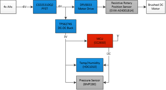
 Figure 2 Smart damper reference design
block diagram
Figure 2 Smart damper reference design
block diagramWith your power topology and management IC chosen, all you have to do now is select the parts and sensors that connect to each of the power rails. TI has a wide selection of power-management ICs and different flavors of MCUs to suit your system needs.
Additional Resources
- Read these E2E™ Community blog posts:
- Design your power stage with Power Stage Designer.
- Take a look at the “Power Topologies Handbook” and “Power Topologies Quick Reference Guide.”