SSZT998 august 2017 AMC1301 , INA226-Q1 , INA229-Q1 , INA240-Q1 , ISOW7821
When I was six years old, I got a remote-control car as a present from my dad. With just a click of a button, I was able to control the car and it was running all around my home. One day, my brother and I suddenly got into a fight and broke the remote-control car into pieces. I was curious to look inside and see how it worked. I learned that remote-control cars used batteries as their main source of energy. I went to my father and asked, “Do all cars operate with batteries?” My father laughed and said, “No, it is impossible to power a car with a battery; only toy cars can operate with batteries. Cars on the road operate with fuel.”
Whenever I remember this story I am quite amazed, because now I work on systems for electric vehicles (EVs), and I know that it’s 100% possible to power a car with batteries. The main source of energy for hybrid EVs (HEVs) and EVs is the battery; efficient control of the battery implies an efficient battery-monitoring system.
The battery-monitoring system is mainly used to estimate state of health (SOH) and state of charge (SOC). In order to obtain detailed information about SOH and SOC, integrating accurate sensors into the battery-monitoring system is important. For a typical battery, current, voltage and temperature sensors measure the following parameters, while also protecting the battery from damage:
- The current flowing into (when charging) or out of (when discharging) the battery.
- The pack voltage.
- The individual cell voltages.
- The temperature of the cells.
Figure 1 shows the location of current sensors in a block diagram of a battery-control unit.
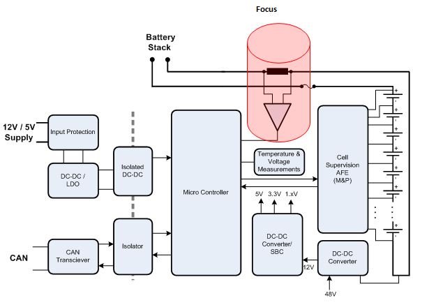 Figure 1 Current-sensor Location in
Battery-control Unit
Figure 1 Current-sensor Location in
Battery-control UnitWhen the battery is the main source of energy for systems in HEVs/EVs, it is essential to have information about its charging and discharging cycles. Current sensors are the main source of information for charging and discharging cycle information by reporting the status of battery SOH to the battery management system. They may be located onboard or externally. With the increase of battery capacities in HEVs/EVs, the requirements on higher current ranges are increasing. Here are the main requirements for a typical current sensor in HEVs/EVs:
- A current range from milliamps to kiloamps for example, 2000A to 2000A, -1200A to 1200A and -500A to 500A. Higher current ranges are required in order to accommodate larger battery capacities, monitor dynamics of the load such as peak current detection (shorts to battery/shorts to ground), and satisfy initial startup/torque demands.
- Higher Bandwidth. Higher bandwidths are required in order to monitor dynamics of the load or respond to fault states. Peak currents are in the kiloamp range and last from milliseconds to few seconds.
- High accuracy. A battery-management system’s ability to accurately measure parameters such as pack voltage, charging/discharging current, individual cell voltages, battery disconnection in abnormal conditions, charge stored by each cell in a stack, operational status of system components for assistance with functional safety, SOC, SOH and state of function (SOF) all depend on the accuracy of the sensor inputs. Accuracy of the current sensor is important, especially at lower currents, to take decisions in a very prompt way to increase system efficiency. Accuracy is normally specified separately for lower and higher currents.
- Temperature and linearity compensation. Temperature and linearity are critical factors in current sensors because of their dependency on temperature. Temperature dependency on the system results in poor accuracy. Maintaining the same accuracy over the entire temperature range is essential. Satisfying this requirement requires a temperature and compensation algorithm.
Battery current sensors can be realized in two ways – shunt and magnetic – as shown in Figure 2.
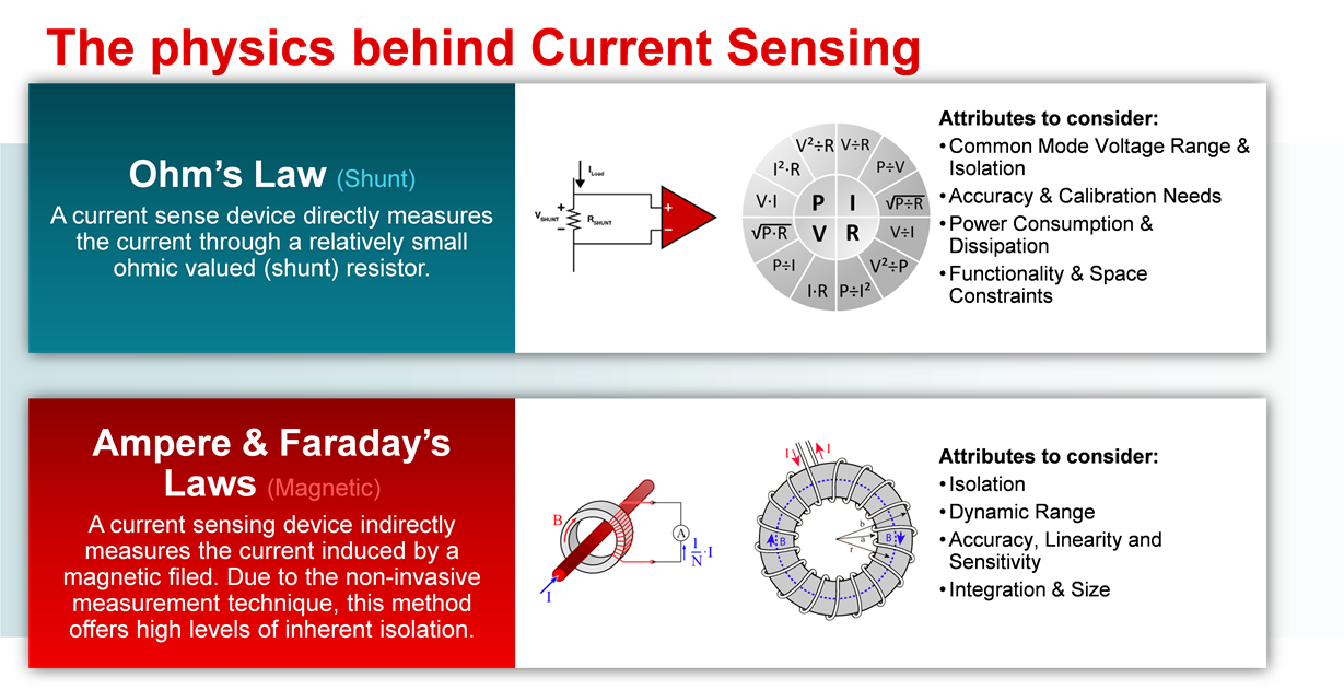 Figure 2 Physics of Current
Sensing
Figure 2 Physics of Current
SensingBoth shunt and magnetic technologies have their own advantages and disadvantages.
Shunt-based Current Sensors
A finite amount of current passes through a shunt resistor; an analog front end (AFE) amplifier measures the voltage drop. With advancements in low-value precision shunts and huge improvements in AFE circuits, shunt technology has been widely adapted for measuring currents in HEVs/EVs. For example, shunts from Vishay offer very low resistance values (50μΩ, 100μΩ, 125μΩ and 500μΩ). With these lower-value shunts, the voltage drop across the shunt is very small. Now the challenge is to measure that tiny voltage drop. TI’s automotive current sensors provide complete solutions for these kinds of systems.
Nonisolated Shunts
The Automotive Shunt-Based ±500A Precision Current Sensing Reference Design offers battery current sensor solutions, providing excellent accuracy and linearity over a grade 1 (-40°C to +125°C) temperature range. Figure 3 shows how the reference design addresses the requirements.
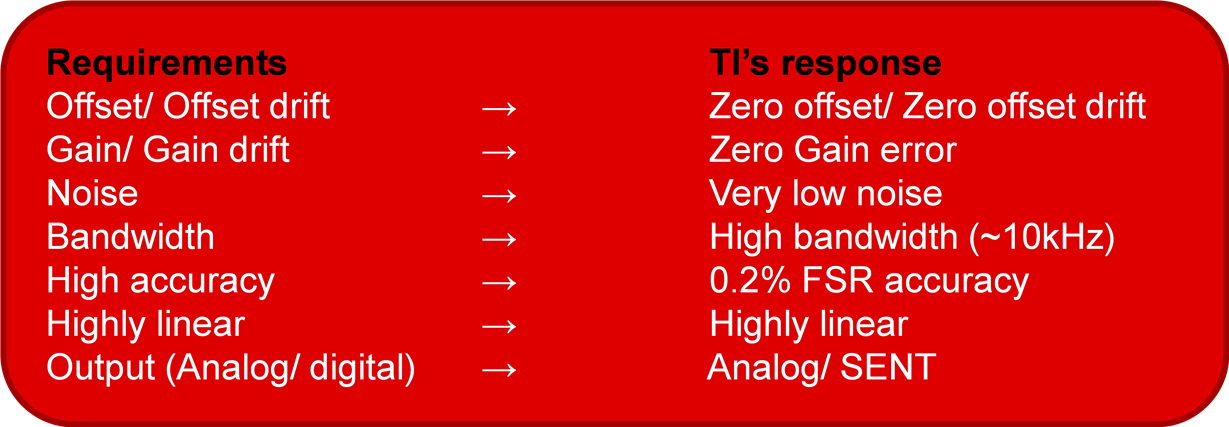 Figure 3 Requirements and TI Response
Offering such performance characteristics over the automotive grade 1 temperature range (-40°C to +125°C) makes this reference design successful in battery current-sensing applications. Signal conditioners like the INA240-Q1 and PGA400-Q1 enable more efficient HEV/EV battery current sensing. Figure 4 shows a block diagram of the main components in a battery current sensor.
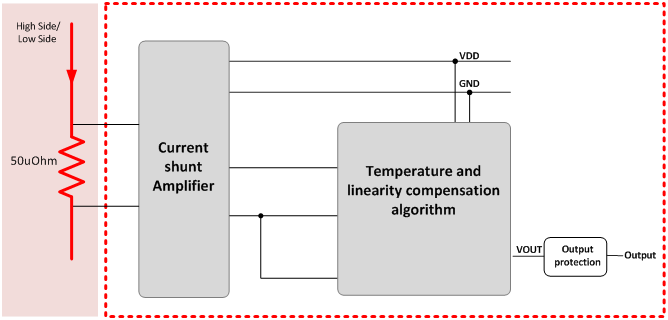 Figure 4 Nonisolated Current Sensor Block Diagram
Isolated Shunts
Devices like the AMC1301 and ISOW7821 offer isolated shunt current-sense measurement. By providing excellent isolation between the hot and cold sides, this system helps with battery sensing reliability. As shown in Figure 5, the AMC1301 provides current signal isolation and the ISOW7821 provides power isolation. The PGA400-Q1 completely eliminates the offset and gain errors.
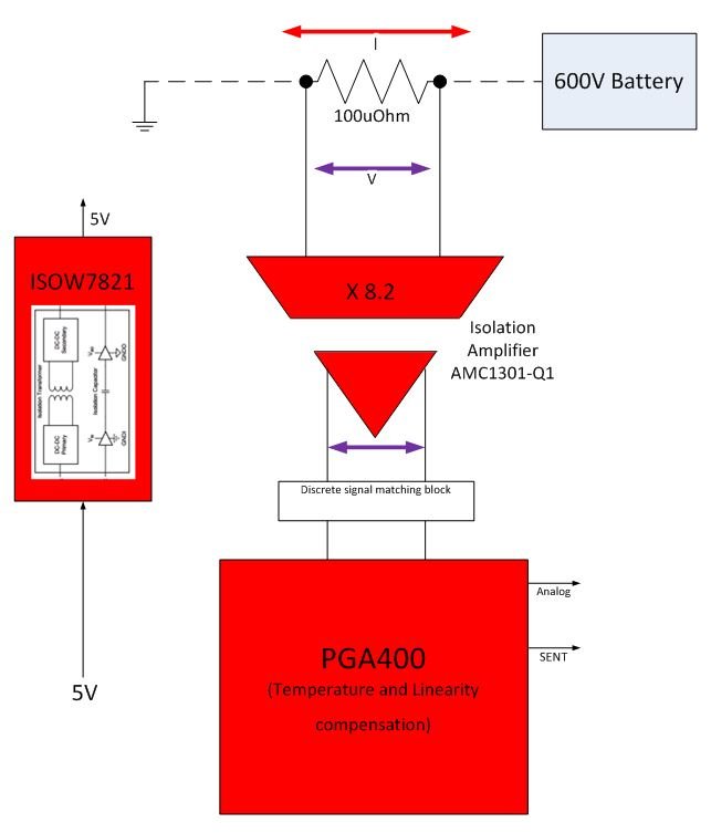 Figure 5 Isolated Current Sensor Block
Diagram
Figure 5 Isolated Current Sensor Block
DiagramOne of the biggest reasons for the evolution of HEVs/EVs is emerging battery technologies. Battery performance, lifetime, safety and reliability play a vital role in HEVs/EVs. A battery current sensor and its accuracy over a wider range are extremely important in order to achieve the required parameters. TI’s battery current-sensing portfolio enables you to achieve these specifications easily and simply.
Additional Resources
- Learn more about technology advancements in HEV/EV.
- Read these blog posts: