SSZTA15 july 2017 DRV8320
Before we jump into the fun, let’s recap from part 1:
- Brushless DC motors are cool (and can help you make friends).
- No one likes talking about the actual hardware (but I’m going to do it anyway).
- There are advantages and disadvantages to both discrete and integrated gate drivers.
I can talk about features and benefits all day long, but what engineers really want to see are some real circuits. In this post, I’ll compare the discrete and integrated gate drive architectures directly to show the board-level differences between the two.
The two key metrics for schematic and layout comparison are number of components and solution size. The first metric - number of components - can be relatively easy to find out after the schematic is completed. The solution size, however, is significantly more complicated to estimate. I often see solution size simply stated at the size of the integrated circuit component. I find that this is very inaccurate, since it does not take into account the external components, any required clearance between components and routing on the board.
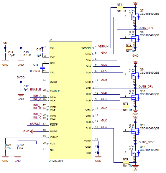
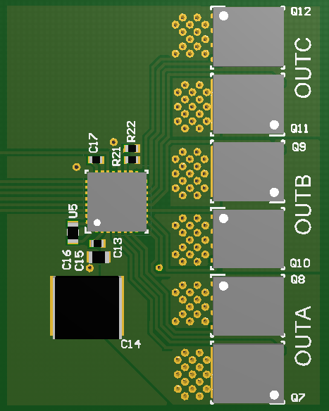
Now, it’s time for show and tell! I spent some quality time in my local design software creating side-by-side schematic and layouts of discrete and integrated gate-driver architectures for a brushless DC motor driver. I chose one of TI’s many discrete gate drivers and the DRV8320 for my integrated gate driver. In addition, I used TI NexFET™ power MOSFETs in standard QFN packages. While this design happened to use standard discrete FETs, TI has just recently introduced two vertically integrated half bridge power blocks that could be used for this application as well, saving even more design space. This exercise certainly taxed my (admittedly) meager schematic and layout skills, but I hope these pictures can be some use to those who want to compare these two brushless DC architectures. If you’d like to view any of the images in greater detail, click the image and it will open in an expanded view.
| Discrete Gate Driver | Integrated Gate Driver | |
|---|---|---|
| Schematic |  |
 |
| 2-D layout | 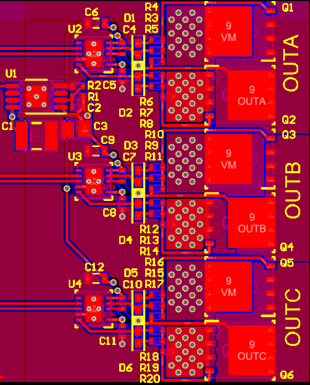
|

|
| 3-D layout | 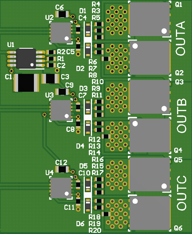
|
 |
| Gate driver layout | 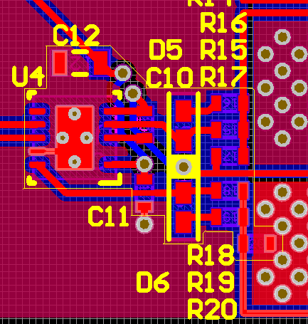 Area: 46.84mm2 (repeated three times) |
 Area: 54.54mm2 |
| Gate drive supply layout | 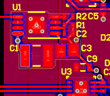 Area: 47.89mm2
 |
Integrated into gate driver |
| Total components | Integrated circuits: 4 Field-effect transistors (FETs): 6 Resistors: 20 Capacitors: 12 Diodes: 6 |
Integrated circuits: 1 FETs: 6 Resistors: 2 Capacitors: 5 Diodes: 0 |
There’s a lot of design and thought thrown into this seemingly quick project. As you can probably guess from above, I decided to create a two-layer board with no internal layers for simplicity in viewing. However, this meant more carefulness was required in layout. As well, the gate-drive setting components on the discrete gate driver and the IDRIVE pin component on the integrated gate driver require adjusting in order to achieve acceptable rise and fall times from the external FETs. There are also many small adjustments in the layout portion that are necessary in order to achieve the smallest size for both solutions. I suppose if I were to detail all of it, I’d have an application note on my hands rather than a blog post (and a lot more readers zoning out or falling asleep).
Thanks for reading along, and I hope this information can be valuable to you in designing a brushless DC motor driver! Due to the popularity of this topic, we have added a Part 3 to this series detailing the differences between integrated and discrete gate driver designs!
I’m still trying to make more friends via brushless DC motors! How are you doing? Do you have any questions about my design? Make sure to subscribe to this blog for more information about motor drives.
Additional Resources
- Read a blog about the demand for increasing power density in power tools.
- Check out the 18V/1kW, 160A Peak, >98% Efficient, High Power Density Brushless Motor Drive Reference Design.
- Learn about the smart gate drive of the three-phase DRV8320.
- Read more about the story of motor drive integration.