SSZTA29 June 2017 TPS25200 , UCC28722
Replacing existing meters (which still use technology developed decades ago), smart meters use a secure connection network to automatically and wirelessly send energy usage to utility companies. The heart of a smart meter is its switch-mode power supply (SMPS) using the low-cost flyback topology for both single- and three-phase smart meters.
The flyback converter shown in Figure 1 operates by first storing energy from an input source into a transformer while the primary power switch is on. When the switch turns off, the transformer voltage reverses, forward-biasing the output catch diode(s) and delivering energy to the output(s). With a flyback topology, an output can be positive or negative (defined by a transformer polarity dot).
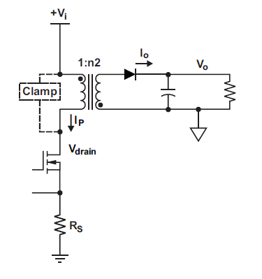 Figure 1 Basic Flyback Block
Diagram
Figure 1 Basic Flyback Block
DiagramFor multioutput, the technique is to have multiple windings on the transformer followed by a diode and capacitor circuit, as shown in Figure 2.
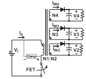 Figure 2 Multioutput Flyback Block
Diagram
Figure 2 Multioutput Flyback Block
DiagramFigure 3 shows the block diagram of a single-/three-phase smart meter’s SMPS scheme. The typical rails are:
- 3.3V for powering the microcontroller.
- 12V for latching relay for connection/disconnection.
- 6V-9V for isolated RS-485/RS-232 interfaces.
- 16V for programmable logic controller (PLC) communications.
- 3.8V-4.2V for Global System for Mobile Communications (GSM)/general packet radio service (GPRS) modem.
- 3.3V for the Sub-1 GHz radio-frequency (RF) module.
- 3.3V for the 2.4GHz RF module.
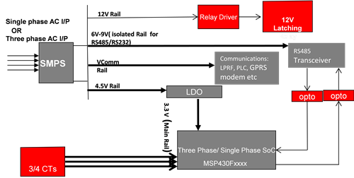 Figure 3 SMPS Scheme in a Smart
Meter
Figure 3 SMPS Scheme in a Smart
MeterIn the multioutput flyback topology used in smart meters, one output is the master and the rest of the outputs are slaves. “One output is the master” means that the feedback loop is closed on that output; hence the master output is well regulated and the rest of the rails are quasi-regulated. Various techniques such as AC stacked winding, DC stacked winding and weighted feedback can improve regulation. But overload/short-circuit protection poses many challenges in a multioutput supply. The pulse-width modulation (PWM) controller will go into hiccup mode on overload or short circuit on any of the outputs. All of the voltage rails will collapse, as well as the main 3.3V rail powering the microcontroller. Because the microcontroller voltage rail has collapsed, it cannot measure energy, defeating the very purpose of a smart meter.
Figure 4 shows a proposed SMPS scheme with TI’s electronic fuse (eFuse) to counter all of the issues and drawbacks mentioned in the present scheme. The TPS25921 can take care of the latching relay, PLC and RS-485/RS-232 interface rails, while the TPS25200 can take care of the Sub-1 GHz, zigbee® and GSM/GPRS modem communications rails.
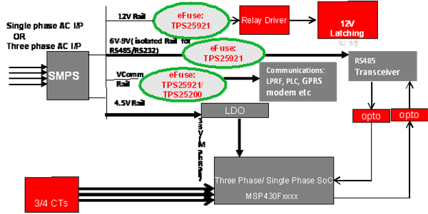 Figure 4 Proposed SMPS scheme in a
smart meter
Figure 4 Proposed SMPS scheme in a
smart meterTI’s eFuse is an active circuit protection device that will limit in-rush current and prevent load damage due to overcurrent events. It has an internal field-effect transistor (FET) to control the load current and integrates overcurrent and short-circuit protection. Figure 5 shows its block diagram.
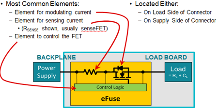 Figure 5 eFuse Block Diagram
The precision overcurrent limit helps minimize overdesign of the power supply, while the fast-response short-circuit protection immediately isolates the load from the input. These devices enable you to program the overcurrent limit threshold with an external resistor. Additional features include overtemperature protection to safely shut down in case of overcurrent and a choice of latched or automatic restart mode.
Thus, the eFuse device will help isolate a rail that experiences an overload or short-circuit event without affecting the main microcontroller rail (3.3V) that is measuring energy.
Additional Resources:
- Download the Precision Power Limiting Solution reference design
- Read the application report, “UCC28722, Bias Supply Design Considerations for Intelligent eMeter Applications.”
- Learn more about flyback SMPS design for smart meters with the Snubberless, Non-Isolated AC/DC Flyback Converter Reference Design with Simplified Transformer
- Check out these other E2E™ Community blog posts:
- Learn more about electricity meter application