SSZTA47 June 2017 TUSB320
With more and more portal devices adopting the USB Type-C™ connector, designing a power bank capable of charging these devices is suddenly a big deal. Unfortunately, the USB Type-C connector is a totally new type of USB connector. Understanding the differences between a USB Type-C power bank from legacy USB power banks is critical for successful product migration.
There actually is not much difference between a USB Type-C power bank power stage and a legacy power bank power stage. The key difference is in how the power path connectivity and device attach/detach detection is handled “From” and “To” the Type-C connector.
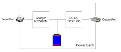
In a legacy power bank there is always an input charging port (such as Micro USB) and one or more output discharging ports (such as USB Type A). A battery charger inside the power bank connects to the input port. A DC/DC converter, mostly a booster, is located at the output path. Figure 1 shows this block diagram.
 Figure 1 A Legacy Power Bank
Pin Connections
The USB Type-C connector is designed for higher power and higher data transmission speeds and has a nonspecific orientation. Its pin assignment has significantly improved from the USB Type A or USB Type B ports.
Figure 2 gives the pin assignments for a full-featured USB Type-C receptacle. There are 24 pins, including several new pairs. However, power bank being a dataless system, it is not necessary to consider the USB 3.1 pins and SBU pins. However D+/D- pins are needed to support BC1.2 and third party proprietary brick IDs. Use below example for connecting Type-C receptacle pins.
- VBUS and GND: there are four pins defined for each net, respectively. Connect all of the pins in same function to share the current.
- D+/D-: Same definition as USB Type A and USB Type B: these are used to transmit the handshake message between power bank and external device. Two pairs are defined in a USB Type C connector but only one set would be connected to the cable. Connect the two pins in same definition directly.
- CC: this is a new channel configuration (CC) pin used for the discovery, configuration and management of connectors across a USB Type-C cable. Connect it to a USB Type-C controller.
 Figure 2 USB Type-C Receptacle Pin Assignments
Adding VBUS Switches
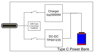
A USB Type-C port is configurable as dual-role port (DRP). A USB Type-C DRP power bank one can charge or discharge via the same USB Type-C port. This will require the addition of a VBUS switch at the USB Type-C receptacle to separate the charger power path and output DC/DC power path, as shown in Figure 3.
A VBUS switch is typically configured as a back-to-back structure so that it can block the energy flow bidirectionally. When the USB Type-C power bank is connected to an adaptor, the VBUS switch on the charging path can be turned on so that the battery can be charged. If the external device is a cellphone, the VBUS switch on discharging path will be turned on while the VBUS switch on charging path is disabled. Generally, a VBUS switch also has three main purposes:
- It can help block energy from the battery to VBUS. The output DC/DC could be a boost converter, which means that the battery voltage can go to the output through its rectifier diode. Using this VBUS switch can block the voltage applied to VBUS before attachment.
- In a USB Type-C power bank, the valid VBUS voltage and current may vary dynamically. You can turn the VBUS switch off if an overcurrent or overvoltage event occurs at the VBUS to protect the post circuit.
- With a USB Type-C DRP power bank, the DC/DC converters for charging and discharging connect to the same port, which requires separating the bulk capacitors for each converter in order to meet the USB Type-C’s requirements for source or sink. The bulk capacitance for a sink is within 1~10uF to limit the input rush current, while the bulk capacitance for a source should be higher than 10uF to keep the VBUS voltage stable.
 Figure 3 A USB Type-C Power Bank with VBUS Switch
Attachment Event Detection
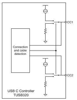
A traditional power bank can detect the VBUS voltage and current to activate the microcontroller (MCU) once an attach/detach event occurs. With the new USB Type-C port, the traditional detection circuits are out of action. The CC line in a USB Type-C connector takes this responsibility. I recommend a Type-C DRP controller such as TUSB320 to implement port attach/detach events in a type C power bank. The built-in CC detection circuit in TUSB320 connects the CC line to its internal voltage source through a pull-up resistor or a current source when configured to source power. The USB Type-C controller will connect the CC to ground via a pull-down resistor when sinking power. Once there is a connection between two devices, the CC line voltage will change. The internal circuit in both devices will detect this voltage variation and start attachment event detection, as shown in Figure 4.
 Figure 4 CC Event-detection Circuit
In summary, with a clear understanding of the pin connections, VBUS switches and attachment event detection, you can easily upgrade a legacy power bank to support USB Type-C devices.
Additional Resources
Check out these TI Design reference designs: