SSZTAB8 march 2017 UCC28700
High-power converters used in server, telecom and industrial systems need auxiliary power supplies to support the housekeeping needs of the power-supply unit (PSU). Due to the ever-growing need for higher power density, these PSUs use an additional add-on card to support their auxiliary needs.

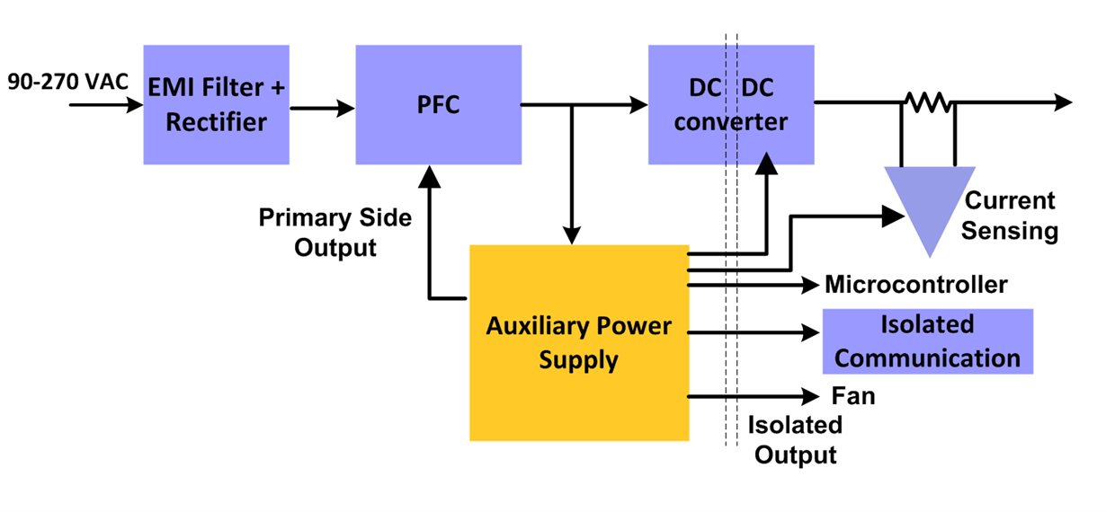
An auxiliary power supply commonly powers the internal control electronics, voltage and current feedback sensing electronics, system fans and biasing supply. It is an isolated DC/DC converter generating multiple isolated outputs to power primary- and secondary-side control devices ranging from 5W to 40W. Figure 1 shows the typical usage of auxiliary power supply in server PSUs.
 Figure 1 System Block Diagram of a
Server PSU
Figure 1 System Block Diagram of a
Server PSUThe auxiliary power supplies are a part of a larger PSU which contains an electromagnetic interference (EMI) filter, diode bridge and bulk capacitor. The bulk capacitor gives us the rectified DC bus, making these supplies independent isolated DC/DC converter. The auxiliary power supplies must have high efficiency over a wide load range (10% load to full load) in order to help the server PSUs meet 80 PLUS platinum/titanium standards, tight regulation, low cost and low standby power, in sizes as small as possible to maintain high power density. The auxiliary power supply also needs to operate over a wide input range (from 100V to 400VDC); have multiple isolated outputs; and keep the system electronics powered under all conditions to detect faults such as undervoltage, overvoltage and overcurrent.
Topology Selection
While selecting the topology of the DC/DC converter for an auxiliary power supply, keep in mind cost, efficiency, the reinforced isolation requirement for the outputs and the form factor. Since you need isolated outputs, your options are limited to flyback, forward, half /full bridge and push-pull converters.
The power level for the auxiliary power supply is usually low, varying from 5W to 40W. This low power-level requirement eliminates half/full-bridge and push-pull converters due to their expense, component requirements and greater losses. And although the efficiency of both flyback and forward converter topologies is comparable, the forward topology uses an extra inductor at the output, which makes it bulkier and more expensive when compared to a flyback converter.
Since a flyback transformer is really a coupled inductor through which power storage and transfer between the primary and secondary occurs, you do not need a separate inductor for storage. And because the other associated circuitry is simple, the flyback topology is thus a very popular topology for low-power-level converters requiring multiple outputs.
Realizing an Auxiliary Power Supply with Seven Outputs
All things considered, the key challenges while building an auxiliary power supply is to provide safe and reliable power while delivering high performance with low power consumption and low bill-of-material (BOM) cost.
Additional resources
- Learn more about stimulating electromagnetic interference from our Power House blog
- Find out how GaN can help with electromagnetic interference
- Download the 25-W, 88% Efficiency, Multiple Isolated Output, Auxiliary Supply Reference Design for AC-DC Power Supply Design Guide
- Learn more about TI’s flyback solutions at www.ti.com/flyback