SSZTAK3 december 2016 TPS65982 , TUSB1002 , TUSB1042I , TUSB1046-DCI , TUSB1046A-DCI , TUSB501 , TUSB522P , TUSB542 , TUSB544 , TUSB546-DCI , TUSB546A-DCI , TUSB551 , TUSB564
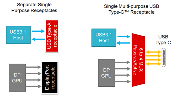
With today’s 4K ultra high-definition (UHD) TVs (and future 8K UHD TVs), as well as solid-state storage speeds, more video and data bandwidth is a must. Interface standards groups in the industry are addressing this trend by enabling more video and data bandwidth. For example, the Video Electronics Standards Association (VESA) DisplayPort 1.4 standard enables 4K and 8K video via four 8.1Gbps (known as high bit rate 3 (HBR3) lanes. The USB Implementers Forum (IF) introduced the USB 3.1 standard to boost data bandwidth from 5Gbps (SuperSpeed or Gen 1) to 10Gbps (SuperSpeed Plus or Gen 2). The USB IF also introduced the USB Type-C standard to bring data and video into a single small receptacle. This USB Type-C connector benefits system developers by enabling the removal of multiple single-purpose receptacles like DisplayPort and USB Type-A and replacing them with USB Type-C, enabling small-form-factor designs (Figure 1). These benefits create their own challenges for system developers.
 Figure 1 Migration to a Single
Multi-purpose USB Type-C Receptacle
Figure 1 Migration to a Single
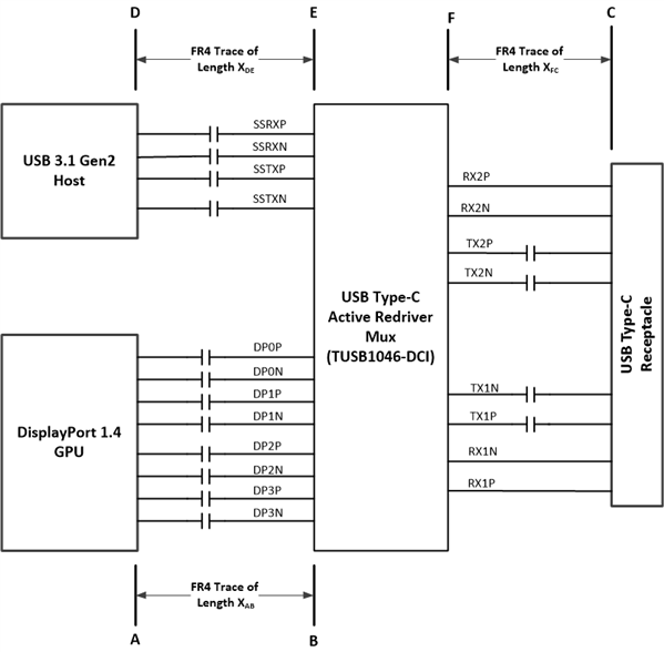
Multi-purpose USB Type-C ReceptacleGraphics processing units (GPUs) and USB 3.1 host controllers are not typically located in the same physical place in the system as depicted in Figure 2. Add to this the need for multiple USB Type-C ports in a product (for example, notebooks may have Type-C ports on the back as well as on the sides), the distance that USB 3.1 and DisplayPort high-speed signals must traverse can become very long. Thus, a USB Type-C active redriver multiplexer (like the TUSB1046-DCI) that can compensate for frequency-dependent loss introduced over long channels is a must for a Type-C system.
 Figure 2 TUSB1046-DCI in a USB Type-C
System
Figure 2 TUSB1046-DCI in a USB Type-C
SystemA frequency-dependent lossy medium, like an FR4 printed circuit board (PCB) trace, will cause attenuated signals and produce a closed eye. This frequency-dependent loss causes inter-symbol interference (ISI).
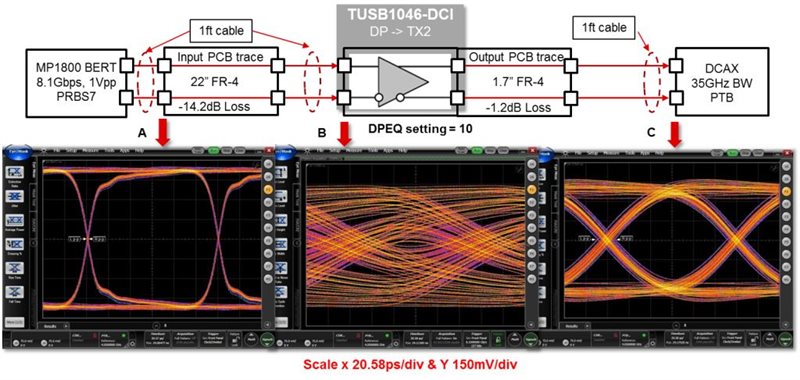
Figure 3 depicts the impact a 22-inch FR4 PCB trace has on an 8.1Gbps pseudorandom binary sequence (PRBS) 7 signal. Before the 22 inches of trace (point A), the eye produced by the bit-error-rate tester (BERT) signal source is open, with little to no jitter. After the 22 inches of trace (point B), the eye is closed entering the TUSB1046-DCI DisplayPort input. The TUSB1046-DCI does its job of correcting the closed eye at the input by outputting a low-jitter open eye (point C) with enough eye-width and eye-height margins to pass DisplayPort 1.4 standard compliance. For optimum performance, choose a specific high-frequency boost (equalization setting) to match the PCB trace loss. In this particular example, an equalization (EQ) setting of 10 was used to match the 14.2dB loss of the PCB trace at 4.05GHz.
 Figure 3 The TUSB1046-DCI’s Impact on
DisplayPort Performance
Figure 3 The TUSB1046-DCI’s Impact on
DisplayPort PerformanceIf you replace the BERT in Figure 2 with a GPU and routed the GPU’s signal through a Type-C passive multiplexer to the Type-C receptacle, the signal at the receptacle would be completely closed and not compliant to the DisplayPort 1.4 standard. A UHD TV connected to such a USB Type-C port would likely not work. But with the TUSB1046-DCI’s ability to compensate for ISI, you can obtain a DisplayPort 1.4-compliant signal at the USB Type-C receptacle.
An active redriver multiplexer can compensate for both DisplayPort and USB 3.1 ISI-related losses and is an excellent solution for systems in which FR4 PCB-related losses require a redriver to produce USB 3.1 Gen 2- and DisplayPort 1.4-compliant signals at the Type-C receptacle. Make your signals compliant quickly, using the TUSB1046 USB Type-C Alternate Mode Redriver Switch Evaluation Module (EVM).
Additional Resources
- The TUSB546-DCI is available for 5Gbps systems requiring a USB3.1 Gen 1 and DisplayPort 1.4 USB Type-C active redriver multiplexer.
- Read the white paper, “USB 3.1 Channel Loss Budgets.”
- Download the data sheets:
- 10Gbps Type-C redriver multiplexer TUSB1046 data sheet.
- 5Gbps Type-C redriver multiplexer TUSB546 data sheet.
- Read more about the TPS65982 USB Type-C and USB Power Delivery controller, power switch and multiplexer.