SSZTAU8 september 2016 SN65DP149 , SN65DP159 , SN75DP149 , SN75DP159 , TMDS171 , TMDS181
High-Definition Multimedia Interface (HDMI) is a popular video interface that uses transition minimized differential signaling (TMDS) as the main communication channel. Each TMDS data lane can support up to 6 Gbps for HDMI 2.0 channels, which is important in maintaining signal integrity over transmission media. This can be quite challenging since the high speed signal suffers loss automatically while transmitting in the data path.
Let’s review the types of signal-integrity degradation that may occur when HDMI signals pass through traces, connectors and cables:
- Insertion loss is the loss of signal power resulting from any obstacles in the signal path.
- Crosstalk is signal distortion caused by capacitive, inductive or conductive coupling from one channel to another channel.
- Inter symbol interference (ISI) is signal noise caused by subsequent symbols. The symbol interval shrinks with higher speeds, so the higher the signal speed, the more prone it is to ISI.
- Signal reflection is caused by impedance mismatch at the connector, resulting in part of the signal reflecting back to the original source rather than transmitting out, thus reducing signal strength at the receiver.
- Jitter is amplitude and phase distortion of a digital signal that can cause flicker on the display image.
Techniques designed to combat these signal-integrity challenges include equalization and clock-data recovery (CDR). An equalizer makes sure that the transmission channel can achieve an equalized frequency response for all frequency components, reducing signal distortion and boosting signal strength. CDR recovers the clock from incoming data and regenerates clean signals, which in turn reduce signal noise and jitter. A retimer is a mixed-signal component that integrates an equalizer and CDR.
A good signal conditioner can support adaptive or fixed equalization to clean up ISI or loss from bandwidth-limited boards and cables. Retimers use CDR circuits to clean up random, phase and sinusoidal jitter. Good retimers have wideband CDR tracking and narrowband jitter cleansing, as well as the capability to work in a wide frequency range. Additionally, a good retimer has selectable source termination to match traces and impedance to reduce reflections in the signal path. A good retimer will also provide several features for passing HDMI 2.0 compliance and reducing system-level design issues, which compensates for the attenuation that occurs when driving long cables or high-loss board traces.
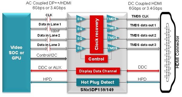
The SN65DP159 is a dual-mode DisplayPort or AC-coupled TMDS-to-HDMI 2.0 retimer supporting all of the features I’ve described. The SN65DP149 is a retimer also contains the same features and supports HDMI 1.4b. Both handle AC-coupled-to-DC-coupled physical layer conversion and are pin-to-pin compatible. Figure 1 is the block diagram.
 Figure 1 SN65DP159/SN65DP149 Functional
Block Diagram
Figure 1 SN65DP159/SN65DP149 Functional
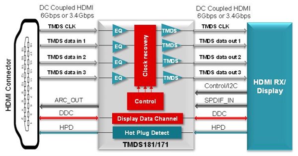
Block DiagramIf the input is DC-coupled TMDS data, TI’s TMDS181 or TMDS171 retimers can be selected for HDMI-to-HDMI support for applications up to 6 Gbps, such as high-definition TV. You should place the retimer at the HDMI connector to compensate for any signal noise propagated into the TV receiver. Figure 2 shows the block diagram.
 Figure 2 TMDS181/TMDS171 Functional
Block Diagram
Figure 2 TMDS181/TMDS171 Functional
Block DiagramBy using the right retimer in your video system, you can enable cleaner signals and a true 4K experience.
Interested in learning more about optimizing signal integrity? Download the white paper, “Build a true fidelity system using video signal conditioners.”