SSZTB27 july 2016 CSD19537Q3
A solid-state relay (SSR) is a semiconductor-based device used for on/off control of a load. The semiconductors typically used in SSRs include two types of power transistors and two types of thyristors. The power transistors include bipolar junction transistors (BJTs) and metal-oxide-semiconductor field-effect transistors (MOSFETs). The thyristors include silicon-controlled rectifiers (SCRs) and triode AC switches (TRIACs).
A small external voltage or current controls these semiconductors. Therefore, semiconductors can control high-output power loads using low-input power. The load current can be either alternating current (AC) or direct current (DC), which will determine the type of semiconductors used to perform the switching functionality. In addition to load control, SSRs can be isolated or non-isolated, depending on the application.
Compared to electromechanical relays (EMRs), SSRs do not have mechanical contacts that can wear out and limit the life of the end equipment. Some examples of end equipment where SSRs can be utilized are heating, ventilation and air conditioning (HVAC) system control, thermostats, programmable logic controllers (PLCs) in factory automation and test and measurement equipment.
Controlling AC Loads
Thyristors and power MOSFETs typically control AC loads. A thyristor is a latching device that starts conducting when the gate receives a current pulse and will continue conducting until the current falls to zero. Within the thyristor family are SCRs and TRIACs. The SCR is a unidirectional and semicontrollable switch that turns off when the load current falls to zero.
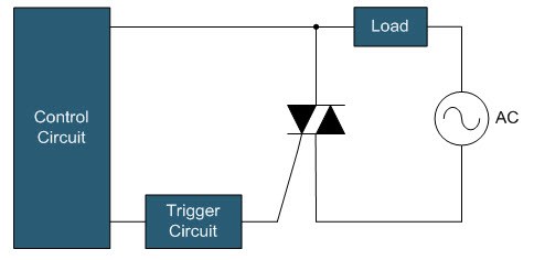
Because of the SCR’s unidirectional functionality, a TRIAC configured with two SCRs in antiparallel controls AC current, as shown in Figure 1. The TRIAC will allow turn-on controllability for both positive and negative current. The delay time for the current to fall to zero would be a maximum of a half cycle, between the removal of the gate-control signal and the current falling to zero. This is non-ideal when controlling turn-off time is necessary. For example, today’s smart thermostats are including more features which require more power. Instead of consuming the extra power from the thermostat batteries, the thermostat can be self-powered by the HVAC power supply. This is only possible if both turn-on and turn-off times are controllable.
 Figure 1 TRIAC SSR with an AC load
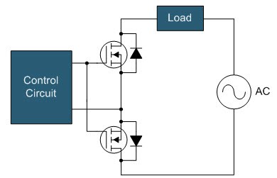
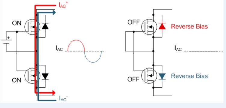
A solution to this problem is the power MOSFET. A power MOSFET is bidirectional but fully controllable in only one direction. By using two MOSFETs in series, as in the configuration shown in Figure 2, it is possible to fully control AC current as well as turn-on and turn-off times of the MOSFETs. Figure 3a shows how current flows through the MOSFETs.
During the off-time, the body diodes of both MOSFETs will block the current flow. The top body diode is reverse-biased for positive voltage and the bottom body diode is reverse-biased for negative voltage, as shown in Figure 3b. The input capacitance and current-driving capability of the gate-driving circuit determine the MOSFET’s turn-on and turn-off times.
 Figure 2 Power MOSFET SSR with an AC load
 Figure 3 Current flow through a MOSFET SSR during on-time (a); and off-time (b)
With their low on-resistance, wide current and voltage capability, and a variety of package options including industrial approved LGA devices measuring all the way down to 1.53 mm by 0.77 mm, it is easy to consolidate your design with TI’s MOSFETs without compromising on performance. For example, the 100V NexFET™ CSD19537Q3 N-channel power MOSFET packaged in a 3.3-mm by 3.3-mm SON package can control AC loads of an HVAC system in a building.
Controlling DC Loads
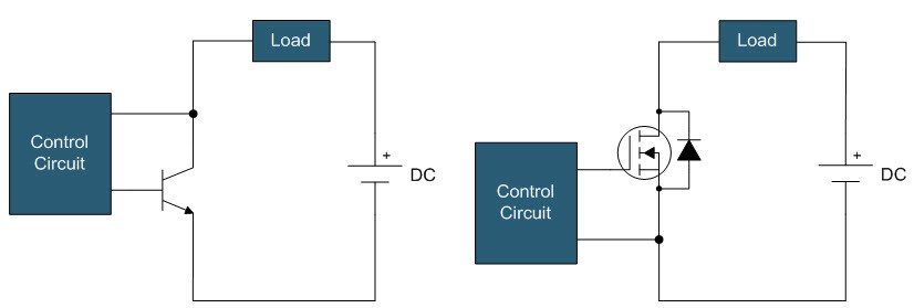
Power BJTs or MOSFETs typically control DC loads. A power BJT is a unidirectional and fully controllable device, whereas a power MOSFET is bidirectional but fully controllable in one direction, as I mentioned earlier. Since the DC current load is one polarity, only one BJT or MOSFET is required, as shown in Figure 4. Both devices require a constant control signal to stay in an on state. SCRs and TRIACs are not suitable for this application because the DC load will not go to zero and enable the devices to turn off naturally. One example of a DC load is a DC motor in home appliances or industrial systems.
 Figure 4 DC load SSR with a power BJT (a); and MOSFET (b)
Isolation
SSRs are used in applications requiring the control of high voltage or multiple loads. Isolation is necessary when combining two or more loads into one system. In such cases, even in low-voltage systems, it is important to use isolation to keep the grounds separate. Two typical methods of isolation used in SSRs are transformer coupling and optoisolator coupling.
In transformer coupling, the control signal applied to the transformer’s primary and secondary sides triggers the power switch. A benefit of the transformer is that the power is transferable along with the signal to the secondary-side circuit.
In optoisolator coupling, a photosensitive semiconductor senses a control signal applied by a light or infrared source like a light emitting diode (LED). The signal from the photosensitive semiconductor triggers the power switch. This method involves no electrical connection between the control input and the load, ensuring electrical isolation. A drawback is that you must supply a separate power supply to the secondary-side circuitry excluding phototriacs.
In cases where isolation is not necessary (such as in low-voltage systems controlling a single load), direct AC and DC control is possible. Direct control is when a control circuit provides the trigger without additional isolation. Due to its simplified design, direct control is preferable when cost is the main objective.
Stay tuned for the next blog providing an overview of self-powered SSRs. In the meantime, if you would like further information about SSRs, leave a comment below.
Additional Resources
- Check out this TI Designs reference design for AC load control:
- Solid State Relay 24V AC Switch with Galvanic Isolation Reference Design (TIDA-00751).
- See the data sheet for the NexFET CSD19537Q3 N-channel power MOSFET.
- Learn about SSRs in thermostats with the “Click! Clack! What’s the setback in your thermostat?” blog post.