SSZTBD3 april 2016 TPS7A85
Living and working in Asia exposes me to a wide variety of interesting support questions. For example, I was recently asked if TI had a cross-device to an LDO controller. This controller is in a small-outline transistor (SOT)-236 package that takes up a 3mm-by-3mm area on the printed circuit board (PCB). Figure 1 shows the recommended schematic for the controller.
 Figure 1 Simple LDO Controller
On the surface, the approach of using a high-current regulator looks good. After learning the design engineer wanted to support a maximum 4A of current from 1.35VIN to 1.0VOUT, I recommended the TPS7A85. The TPS7A85 is not a controller, but it is a fully integrated 4A LDO voltage regulator that comes in a 3.5mm-by-3.5mm 20-pin quad flat no-leads (QFN) package. Obviously, that package is a little larger than the SOT-236.
The immediate response was, “The TPS7A85 is too complicated.” There are cases where more pins equals more complexity; however, in the case of the TPS7A85, more pins actually translates into fewer components. See the equivalent TPS7A85 schematic in Figure 2, where the external component count decreases from nine to five.
 Figure 2 The TPS7A85 as a 4A
Ldo
Figure 2 The TPS7A85 as a 4A
LdoWhy are there four fewer components? The TPS7A85 incorporates TI’s ANY-OUT feature, which allows users to dynamically set VOUT with voltage-setting pins. Whenever one of these pins is grounded, the voltage adds to the internal 800mV reference. So by grounding the 200mV pin, VOUT instantly becomes 1.0V.
With this feature, you can change the voltage from 800mV to 3.95V simply by grounding the appropriate voltage-setting pins to create the desired output voltage. The quantifiable benefits of this approach are:
- 1% guaranteed output regulation.
- No need to buy precision-feedback resistors to set VOUT (you can still use the FB pin with external resistors if you wish, of course).
- The ability to dynamically set VOUT in the application.
With an LDO controller, the overall efficiency is only 1/1.35V, or 74%. The total power dissipation in the power FET is worst-case 4A ×4350mV, or 1.4W. Turns out, that is the same efficiency you get with an LDO regulator.
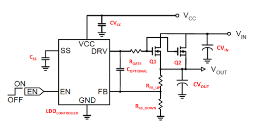
To manage the thermals, the controller uses two external FETs to help spread the heat, as shown in Figure 3.
 Figure 3 An LDO Controller Driving Two
Pass FETs
Figure 3 An LDO Controller Driving Two
Pass FETsIf you wish to do use a controller, I recommend adding another RGATE to help make sure the gate-drive layout is as symmetrical as possible so that Q1 and Q2 share the current properly. In this application, the FETs are in a 5mm-by-6mm package, which takes up more than six times the area of the controller itself.
The TPS7A85 package is only 3.5mm by 3.5mm, so its thermal performance may not be as good as the LDO controller. But let’s compare the difference. With the controller, the FETs have a temperature from junction to ambient thermal resistance (TJA) of 25°C/W. Thus, at peak current with the power dissipation at 1.4W, the temperature rise should be around 1.4W × 25°C/W, or 35°C. The temperature rise would be 17.5°C per FET – assuming that the FETs share the temperature rise evenly. That seems pretty robust. How does it compare to the TPS7A85?
The TPS7A85 has a TJA of 35.4°C/W, so at peak power the temperature rise is 1.4W × 35.4°C/W, or 49.6°C. On the surface this looks worse, but is it? Consider some of the real advantages that an integrated LDO regulator has over an LDO controller:
- Thermal shutdown – The LDO controller does not have the ability to monitor the FET temperature. The TPS7A85 does.
- Current limit – The LDO controller’s only job is to regulate VOUT. It has no ability to limit current or shut down when the load current is too high. The TPS7A85 does.
- Stability – If you want to ensure that the LDO controller is stable with the FET(s) and parasitic capacitances and inductances in the application, you would have to add additional components to measure loop stability. With the TPS7A85, you would not.
- Size – The LDO controller takes up a lot more area because of the external FET. The TPS7A85 does not.
- Accuracy – The LDO controller in this application has an overall accuracy of 2.5%. When considering the external resistor’s worst case, this is 4.5%. The TPS7A85 overall accuracy is better than 1%.
- Noise – The LDO controller does not even mention this on the data sheet. The TPS7A85’s noise is ~5μVRMS 10-100KHz at 1VOUT.
The last two advantages in this list are worth highlighting, as most applications choosing an LDO controller or LDO regulator over a DC/DC converter are doing so to power precision VCORE rails for FPGAs or DSPs, or precision ADCs/DACs.
To sum it all up, the LDO regulator approach seems to be the simplest way to get the job done. Consider TI’s TPS7A85 high-current, high-accuracy, low-noise LDO voltage regulator for your next design. Order the TPS7A85 evaluation module now.
Additional Resources
- Read the application report, “ANY-OUT Low-Dropout Regulator Controlled by I2C™ IO Expander Device.”
- Search for other TI LDOs.