SSZTBF0 April 2016 LM2574 , LM2574HV , LM2575 , LM2576 , LM2576HV , LM2590HV , LM2591HV , LM2592HV , LM2593HV , LM2594 , LM2594HV , LM2595 , LM2596 , LM2597 , LM2597HV , LM2598 , LM2599 , LM2672 , LM2674 , LM2675 , LM2676 , LM2677 , LM5575
This article was co-authored by Harrison Overturf and updated in August 2020.
TI’s SIMPLE SWITCHER® LM2576 regulator has been a popular choice for DC/DC buck regulation for over 20 years. But with so many different regulators out on the market, it may seem difficult choosing the right part for the job. Here’s what to look for when you are choosing between seemingly identical products.
To facilitate this discussion, let’s evaluate similar pin-to-pin (P2P) drop-in alternative devices made by other manufacturers against TI’s SIMPLE SWITCHER LM2576. Let’s call these similar products “regulator X.” The data sheet for regulator X closely resembles the data sheet for TI’s regulator; in fact, it may look identical. To test how well the performance of regulator X matches its stated critical parameters such as switching frequency and current limit, the applications engineering team at TI created a custom evaluation board to take performance and reliability bench data on TI’s 40-V, 3-A LM2576 buck converter, as well as three other regulator X devices – which I’ll call Xa, Xb, Xc – from various manufacturers.
All four devices were evaluated for efficiency across input voltage and load current for a common 5-VOUT application. Tests were conducted at temperatures of -40°C, 25°C and 85°C. Output current was also tested all the way to 7 A on the nominal 3-A devices in an effort to reveal performance limits, safety risks and reliability risks.
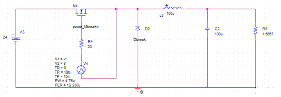
Test results showed that at least one manufacturer's device switched at a frequency nearly three times the stated frequency in the device data sheet. The measured switching frequency was 150 kHz while the device is rated to switch at 52 kHz according to the manufacturer’s data sheet. Accurate knowledge of the device switching frequency is critical to properly sizing external components for your design. If the switching frequency of your chosen device is lower than expected, external component ratings such as primary output inductance will be too small. This may lead to a host of problems including output inductor current saturation, output capacitor damage due to higher root mean square (RMS) current, and system instability. If the switching frequency is higher than expected, the component ratings will be too large and not fully optimized for the application, leading to wasted board space. The importance of accurate knowledge of switching frequency cannot be understated. Figure 1 shows a simple buck schematic which was simulated at varying switching frequencies using PSpice® for TI tool. PSpice for TI is a free-to-use circuit simulation platform that allows the user to simulate TI devices before committing to layout and fabrication, thus reducing time to market and development costs.
 Figure 1 Simple Buck Simulation
Schematic
Figure 1 Simple Buck Simulation
SchematicThe pulse width and period of the pulsed voltage source were varied to achieve three distinct switching frequencies: slow (20 kHz shown in red), nominal (52 kHz shown in green), and fast (150 kHz shown in blue). The resulting simulated inductor current waveforms shown in Figure 2 illustrate the effect of changing switching frequency on inductor current ripple. This inductor current ripple is shunted through the output capacitor, providing a smooth DC output current to the load. Table 1 illustrates how increased peak to peak inductor ripple current results in higher RMS current through the output capacitor. The higher RMS current for the slow switching frequency case would likely cause damage to output capacitors rated for the nominal or fast switching frequency cases.
 Figure 2 Simulation Output of Inductor
Current Waveform at Varying Switching Frequencies
Figure 2 Simulation Output of Inductor
Current Waveform at Varying Switching Frequencies| Switching frequency (kHz) | Inductor current ripple (mA) | Output capacitor RMS current (mA) |
|---|---|---|
| 20 | 2300 | 1030 |
| 52 | 890 | 830 |
| 150 | 280 | 795 |
The most common performance inaccuracy found during testing was in the stated vs. actual current limit. High current limits cause excessive inductor, diode, and integrated circuit (IC) heating during short-circuit conditions, which can damage the IC and prevent it from functioning correctly. This in turn can prevent the end product from functioning. On the data sheets for regulators Xa, Xb and Xc, the stated maximum current limit is 6.9 A. However during evaluation, it was found that regulators' Xa, Xb and Xc current limits actually ranged from 4.9 A to 7.5 A; see Table 2.
| 12 Vin | 24 Vin | 36 Vin | |
|---|---|---|---|
| TI's LM2576 | 4.49 A | 4.71 A | 4.89 A |
| Manufacturer Xa | 5.67 A | 6.04 A | 7.00 A |
| Manufacturer Xb | 4.92 A | 5.25 A | Can't Start |
| Manufacturer Xc | 6.01 A | 6.89 A | 7.56 A |
This article has focused on the importance of accurate knowledge of switching frequency and current limit, but how will you know these parameters are accurate when selecting a buck converter for your next design? Here are a few steps you can take to help ensure your buck converter design works as expected:
- Double check the data sheet to ensure design requirements are met within device specifications; the absolute maximum ratings section and electrical characteristics table are good places to start.
- Post your question on an online forum such as E2E.
- Request an evaluation module (EVM) for testing.
Additional Resources:
- Check out this training video, "Practical Comparisons of DC/DC Control Modes - Switching Frequency Considerations."
- Learn more about simulating your design with PSpice for TI with a training video, "PSpice for TI: Introduction."
- Read this technical article, "How to increase system reliability and simplify design using DC/DC converters."