SSZTBS1 december 2015 CSD18509Q5B , DRV8701
There’s a saying that great engineers do not just discover problems, they solve problems.
In my last post for this series on top FAQs, I explained exactly what electrical overstress (EOS) is, how it affects integrated circuit (IC) components, and several common sources of EOS in motor-drive systems (based on the saying above, that is the “problem”). One of my colleagues also covered supply pumping, a common source for EOS. But what steps can you take to prevent EOS (the “solution”)? In this post, I’ll walk through some of the more common methods that system designers can use to prevent or protect against EOS in motor-drive systems.
Design With Margin
In lieu of investigating elaborate protection schemes and devices, one of the most common methods is to design a system with sufficient operating margin.
I’ll give a simple example. An AC/DC converter generates a 24 V power supply for a simple brushed DC motor-drive system. The DRV8701 H-bridge gate driver and CSD18509Q5B power MOSFET drives a brushed DC motor and are supplied directly from the 24 V.
In an ideal case, the 24 V supply is exactly that: 24 V. In the real world, the 24 V varies due to different load conditions, parasitics and regeneration currents from the motor. Being able to understand the supply-voltage variation allows you to select components with proper voltage ratings. It is not uncommon to see up to 2x margin on component ratings in motor-drive systems. In Figure 1, the DRV8701 supports up to 45 V and the CSD18509Q5B supports up to 40V to tolerate variation and transients in the supply voltage.
 Figure 1 Brushed DC Motor-drive
System
Figure 1 Brushed DC Motor-drive
SystemUse Bulk Capacitance
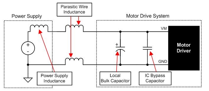
Another common method is what I call “throwing” bulk capacitance at the issue. This can be as unsophisticated as it sounds or as complex as creating a detailed simulation that accounts for parasitics and motor response using different bulk-capacitance sizing. Large ceramic or electrolytic (bulk) capacitors provide a local repository for charge. The large capacitor allows the system to provide the charge required in a load step or source the charge generated during motor regeneration without excess voltage transient. Figure 2 is an example of local bulk capacitance.
 Figure 2 System with Bulk
Capacitance
Figure 2 System with Bulk
CapacitanceAlmost all motor-drive systems are designed with some amount of bulk capacitance, although the size depends on the specific system. Some factors are:
- The highest current required by the motor system.
- The power supply’s capacitance and ability to source current.
- The amount of parasitic inductance between the power supply and motor system.
- The acceptable voltage ripple.
- The type of motor used (brushed DC, brushless DC and stepper).
- The motor braking method.
Add Transient Voltage Suppressors
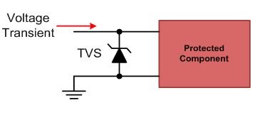
If the previous two methods still don’t provide enough protection from EOS, transient voltage suppressor (TVS) diodes are the next most commonly used protection scheme. TVS diodes operate by shunting excess current when the induced voltage exceeds the breakdown level of the TVS. The TVS will automatically reset when the overvoltage condition goes away. It’s important to understand several parameters of the TVS, including:
- Leakage current: current conducted when the device is off.
- Breakdown voltage: when significant conduction occurs.
- Clamping voltage: when the device will conduct the fully rated current.
- Power rating: how much energy the device can safely conduct.
You should also be well aware of the parasitic capacitance and inductance of the device, which might limit its effectiveness.
 Figure 3 TVS Protection Scheme
Some of the common downsides associated with TVS protection schemes are related to their size and cost. The size of the TVS directly relates to the amount of energy that must be removed from the system during the voltage transient.
These are just some of the more common methods of protecting against EOS; a multitude of other methods exist. If you have an EOS solutions or experiences to share or topics you’d like to see in future blogs, please log in to comment below. If you have specific question, you can search or ask the Motor Application Team on the E2E™ Community Motor Drive forums.