SSZTBS3 December 2015 LM74610-Q1
When you fly on an airline, you’ll occasionally hear “Thank you for flying with X; we know you have many choices when you fly.” Similarly, engineers have many choices when it comes to picking reverse-polarity solutions. Some of the choices include diode, P-channel field effect transistor (PFET), and TI’s LM74610-Q1 plus N-channel field effect transistor (NFET) (called a smart diode solution). In this post, I’ll highlight some key aspects of all three solutions with regards to automotive applications.
I will pick a couple of application specific parameters for comparison purposes: thermals, dynamic reverse polarity, voltage interruption, continuous power-line disturbance and quiescent current (Iq), and leakage current.
1) Thermals
Thermals are usually the deciding factor when choosing between a diode solution and a FET solution. Figure 1 shows the board I used to compare. The smart diode is the “coolest” solution and shows the lowest temperature rise seen in Figure 2. The temperature rise of PFETs is much higher if the input voltage drops to 6V (similar to start-stop voltages), since the Rdson increases dramatically at lower input voltages. Of course, take one look at the diode temperature and you’ll say “ouch.”
 Figure 1 Board Used for Comparison of
Thermal
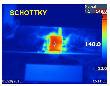
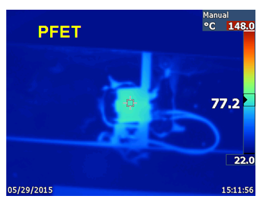
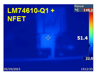 Figure 2 Thermal Measurements with
10A Current and vIN = 6V
Figure 2 Thermal Measurements with
10A Current and vIN = 6V2) Dynamic Reverse-Polarity
The dynamic reverse-polarity requirement comes primarily from standards testing requirements such as ISO7637 and OEM-specific requirements. You can use diodes, PFETs and NFETs but their performance is related to other component values. Figure 3 illustrates how diodes and a smart diode solution are very similar in performance, whereas with the PFET solution the voltage goes negative (depending on the output capacitor used). Due to the slow response time, you will need bigger output capacitors, as shown in Figure 4.
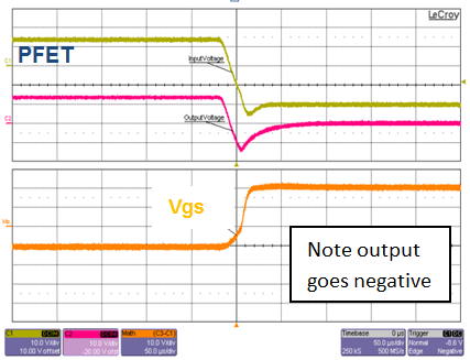
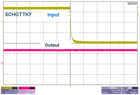
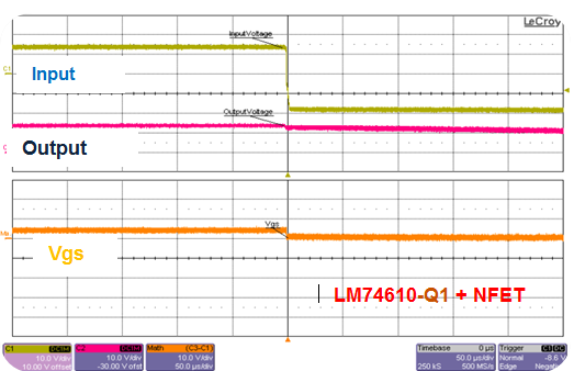 Figure 3 Dynamic Input Voltage
Reversal, 12V to -20V, Cout = 4.7µF, Io = 0.1A
 Figure 4 Dynamic Input-voltage Reversal, 12V to -20V, Cout = 2200µF, Io = 0.1A
3) Voltage Interruption
The voltage interruption requirement comes specifically from OEM specifications and is meant to simulate loose contact at the battery terminal or module wiring. As shown in Figure 5, diodes and the smart diode solution are very similar in performance, whereas with the PFET solution the voltage dips very low. The name of the game is to keep the output voltage high for small voltage interruptions. In the case of interruptions, reverse current flows from the output capacitors back into the input. In the case of diodes and the smart diode solution, the reverse current is blocked. The PFETs allow reverse current back and hence deplete the output capacitor. In practice, this means less hold-up time for an interrupt event.
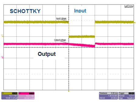
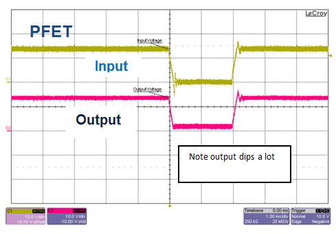
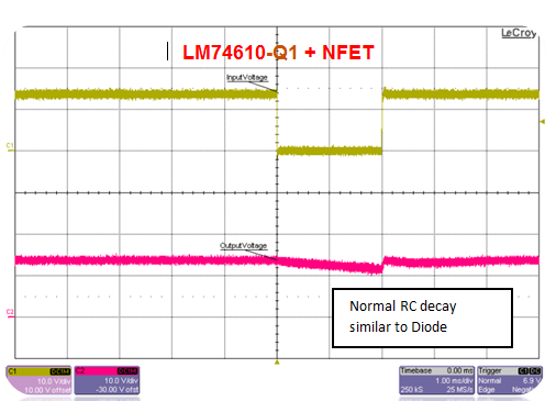 Figure 5 Voltage Interruption, 12V to
0V, T = 2ms, Cout = 100µF, Io = 0.1A
Figure 5 Voltage Interruption, 12V to
0V, T = 2ms, Cout = 100µF, Io = 0.1A4) Power Line Disturbance/Superimposed AC Voltage
The continuous power-line disturbance requirement comes from the fact that alternators create noise/AC ripple on DC voltages. The AC ripple at different frequencies can cause high ripple current if reverse currents are not blocked. The repercussions of high ripple current are lower reliability for the electrolytic capacitors and higher temperature rise. Figure 6 shows the difference in ripple currents: 5KHz for a diode, 7A for the smart diode solution and 25A for the PFET.
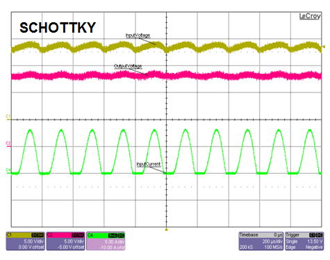
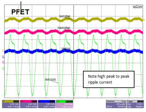
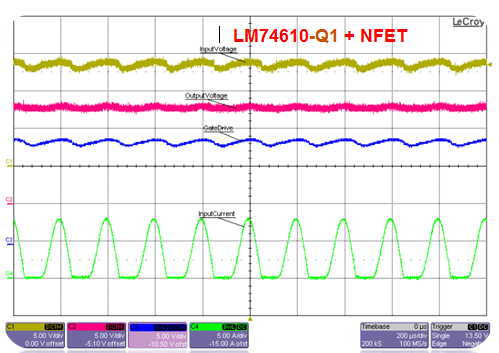 Figure 6 Superimposed AC Voltage, 2V
Peak to Peak at 5KHz and Io = 3A
Figure 6 Superimposed AC Voltage, 2V
Peak to Peak at 5KHz and Io = 3A5) Quiescent Current
Quiescent current is a big, big deal for automotive applications. A complete module is allowed a maximum 100µA for standby currents (Iq). The smart diode solution mimics a diode with zero Iq. With a PFET solution, the Iq can be higher than 100µA unless you use additional circuitry to turn off the gate-drive bias.
6) Leakage Current
Leakage currents are often overlooked in most single input applications. How it plays a role in real-world scenarios is sometimes confusing. Let’s take an ORing application with two diodes. If one of the inputs turns off, you would expect the voltage at this point to be zero. Due to some leakage current, however, the voltage from the output leaks back into the input and you see some voltage there. If you draw more current from the input than the leakage spec, the voltage will drop to zero. Schottky diodes have low leakage currents at 25°C but go much higher at high temperatures. For example, a MBR1545 diode has 1.5µA of leakage at 25°C and 1mA at 125°C. PFET solutions have infinite leakage, since they allow current to flow back into the input if the FET is not turned off. In comparison, the smart diode solution has leakage of 60µA at 25°C and 110µA at 125°C.
After making all of these comparisons, it can be seen that the smart diode solution (a LM74610-Q1 plus NFET) is superior to both diodes and PFET-based schemes used in reverse-polarity designs for automotive applications. As I had mentioned in the beginning, when you are ready to dive into your next design of a reverse polarity solution, I hope you will do a test drive of the smart diode solution considering the various advantages it brings to the table.