SSZTBX5 november 2015 LM43603-Q1 , LM53603-Q1
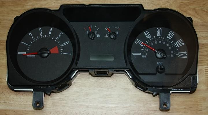
Remember when instrument clusters used to be boring? There were typically only five functions: a speedometer, tachometer, mileage, fuel gauge and temperature gauge.
 Figure 1-1 In the Old Days, Instrument
Clusters Were Much Simpler and Required Much Less Power.
Figure 1-1 In the Old Days, Instrument
Clusters Were Much Simpler and Required Much Less Power.Fancy models showed your speed in both miles per hour and kilometers per hour, in case you finally caved and agreed to take that road trip to Winnipeg that your spouse was always talking about. All of the dials were mechanical. The only graphics were of a gas pump and what looked like a key sticking out of a body of water.
 Figure 1-2 Older Instrument Clusters Had
Very Limited Graphics, Including This Skeleton Key Emerging from a Body of
Water.
Figure 1-2 Older Instrument Clusters Had
Very Limited Graphics, Including This Skeleton Key Emerging from a Body of
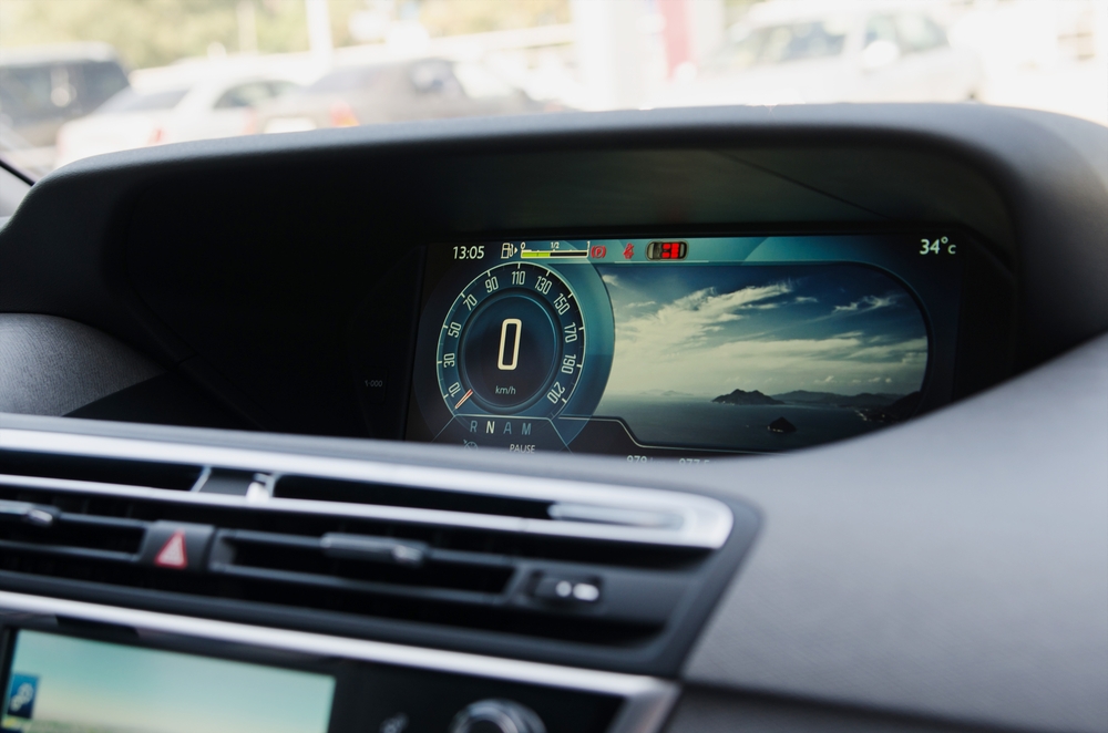
Water.Over the last few years, instrument clusters have started getting a lot more interesting. In case you haven’t yet upgraded your ’81 Scirocco, they are way prettier now.
 Figure 1-3 Today, Instrument Clusters
Were Digital and Require More Power.
Figure 1-3 Today, Instrument Clusters
Were Digital and Require More Power.Most clusters these days are digital, with LCDs and LEDs used for backlighting (Figure 1-3). In fact, if you only have a 3.5-inch display, that’s considered low end. The trend is moving toward 7 inches, while 12 inches is standard for those who can afford high-end vehicular transportation. And, of course, you can easily control the display by manipulating buttons on the steering wheel. You can view everything going on with your car right from the dashboard, from what song you’re listening to (complete with album art), to vehicle diagnostics, to a 3-D representation of the surrounding area.
All of these enhanced features require a lot more processing power. The sweet spot for off-battery converters is now in the 15W range (5VOUT x 3A) for low-end and mid-range clusters. High-end clusters with massive displays can exceed 25W.
Beyond the fundamental specs of input voltage and output current, perhaps the next-most-important number in the data sheet is the quiescent current (IQ). Actually, make that the next two numbers. Shutdown quiescent current is when the regulator IC is completely disabled via an enable or shutdown pin. Standby quiescent current, on the other hand, occurs when the device is enabled, but has no load.
With the increased electrification of the car, more and more electronics are connected to the 12V battery. Some of these electronics are never completely disabled. Think of your key fob. On the other end of that signal is circuitry for a system called passive entry, passive start (PEPS). The PEPS system must be “on” at all times, waiting for a signal from your key fob. (Otherwise, you might actually have to use the actual key on your keychain, and we don’t want that.) Anyway, because the PEPS system is always on, it is always pulling standby quiescent current from the battery.
In the cluster, several circuits are always on, just like in a PEPS system. Examples include the real-time clock, CAN/LIN transceiver and microcontroller. A typical budget for total current consumption allowable in the standby state for the entire cluster may be 100µA, which is not easy to achieve when the processor may easily take up half of that.
There are different ways to approach the challenge of minimizing power-supply quiescent current in the cluster. Because there weren’t many low-quiescent-current switching regulators until recently, the most common approach was to use a low-quiescent-current LDO in parallel with the switcher. The switcher would be disabled, and the LDO would be available to awaken the downstream circuitry while drawing less current from the battery.
Now that there are devices like the LM43603-Q1 with 27µA standby quiescent current, you can eliminate the LDO altogether. This translates into significant BOM cost savings. And keep in mind that this is 27µA for a synchronous device – a nonsynchronous device data sheet will give you the standby quiescent current for the IC only, not including the diode. Current leakage through the diode can be as high as 1mA at high temperatures, blowing your budget away.
In those cases where you need to eliminate every possible microampere to meet an extra aggressive quiescent current budget, the new LM53603-Q1 is an even better fit. You might look at the data sheet and see 23µA and think it’s not that big of a difference. But the LM53603-Q1 has a fixed output voltage, and, thus, no feedback resistors are required. Current leakage through feedback resistors can easily add another 3-5µA to your system.
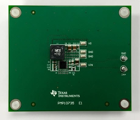
While eliminating hidden sources of quiescent current in your system, these synchronous devices also hit the aforementioned 15W sweet spot for cluster power. If you are the kind of engineer who appreciates excellent performance with fewer external components to deal with, check out one of the 2-layer reference designs featuring the LM53603-Q1 and LM43603-Q1 below (Figure 1-4).
 Figure 1-4 PMP10735 Is a Wide Vin, 3A
Buck 2-Layer Reference Design for Automotive Cluster with CISPR 25 Class 5
Compliance TI Design.
Figure 1-4 PMP10735 Is a Wide Vin, 3A
Buck 2-Layer Reference Design for Automotive Cluster with CISPR 25 Class 5
Compliance TI Design.Additional Resources
-
Consider TI’s SIMPLE SWITCHER® LM43603-Q1 and LM53603-Q1 voltage converters for your next design.
-
Watch a video for hints on reducing quiescent current draw with front-end protection circuitry.
-
Download these tested reference designs:
-
Start a power-supply design with TI’s WEBENCH® Automotive Design Tools.