SSZTC88 September 2015 UCD3138 , UCD3138064A , UCD3138A
In part 1 of this blog series, I talked about how to design a digital power supply using Texas Instruments' UCD3138 as an example and focusing on the hardware design. In this installment, I’ll explain how to write firmware to make it work.
Firmware
Unlike analog power-converter design, which controls everything by hardware, the firmware is the “soul” of digital control; almost all major functions are implemented through code. Because the code is subject to real-time constraints with limited central processing unit (CPU) bandwidth, it is very important to have a well-organized firmware structure.
You can divide the tasks the CPU handles into two categories: time-critical and non-time-critical. Time-critical tasks include ADC measurements, loop control, system protection and state machine. Non-time-critical tasks usually include PMBus/universal asynchronous receiver/transmitter (UART) communication, fault logging, etc.
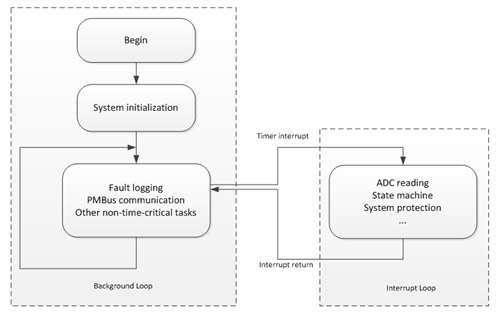
Based on these two categories, the firmware is divided into two major parts: the interrupt loop, which handles time-critical tasks; and the background loop, which handles non-time-critical tasks. Figure 1 illustrates the firmware structure:
 Figure 1 Firmware Structure
The block diagram of the background loop is simple: After system initialization, the CPU goes into an infinite loop. All non-time-critical tasks are performed in this loop. In the meantime, a timer generates interrupts with a fixed frequency. If at any time there is an interrupt, the CPU will stop what it is doing, store all related data and jump to the interrupt routine. Once the interrupt routine is complete, the CPU goes back to the background loop and continues from where it stopped.
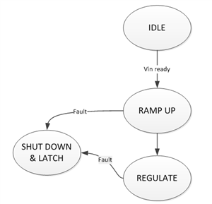
The interrupt loop is more complicated. It measures the ADC inputs, controls the converter and is responsible for system protection. The key part of the interrupt loop is the state machine, which indicates the current state of the converter, what the converter needs to do in this state, and what the converter should do next. Figure 2 is a simple state machine example:
 Figure 2 State Machine Diagram
The CPU continues monitoring the input voltage. Once the input voltage goes above a pre-defined threshold, the converter turns on and begins to perform a soft start, while the output voltage linearly increases until it reaches a set point. Once the output voltage reaches that set point, the converter enters regulation mode, where it will stay until a fault occurs or it is commanded to turn off. If at any time a fault occurs, the converter will shut down and latch, unless commanded to restart.
Using the GUI
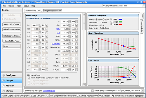
TI’s Fusion Digital Power Designer graphical user interface (GUI) facilitates UCD3138-controlled power-converter designs. By talking to the GUI through the PMBus, you can monitor the power-supply operating status, configure operation parameters and tune the control loop on the fly.
The GUI supports the most popular topologies, including PFC, LLC and phase-shifted full bridge. Different topologies will have different GUI interfaces. A setup ID in the firmware tells the GUI what the topology is so that it will open an interface to accommodate that topology. Figure 3 shows a GUI for a PFC converter:
 Figure 3 UCD3138
Gui
Figure 3 UCD3138
GuiCommunication
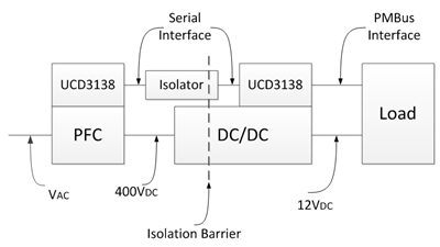
A digital controller can monitor the converter and communicate with the host; in turn, the host can send commands to the converter to perform tasks such as output-voltage adjustment, power-on sequencing, remote on/off control, etc. In an isolated AC/DC application, a PFC is followed by an isolated DC/DC converter, UART is used for communication between PFC and DC/DC, and PMBus is used for communication between DC/DC and load/host, as shown in Figure 4.
 Figure 4 Communication in an Isolated AC/DC System
For UART communication between PFC and DC/DC, there is no industry standard protocol at this time; however, the UCD3138 team has developed a complete primary/secondary communication protocol example ready for use.
Hopefully by now you get a rough idea of how to design a digital controlled power supply. Although the design example I gave in this series is based on a boost converter, the same design principle applies to other topologies. The power stage is the same compared to analog solutions, but the control implementation is different: one is implemented through the code and can be dynamic changed, while the other is implemented hardware and is fixed. Firmware development takes lots of work in digital converter designs. Writing code may be a challenge for analog engineers, but once you get used to it, you will enjoy the advantages of digital power.
Additional Resources
- Download the UCD3138 data manual.
- UCD3138 control theory
- Read the TI application note, UCD3138 PFC Tuning
- Download the Fusion Digital Power Designer GUI for Isolated Power Applications user guide.