SSZTCF2 July 2015 LM22672 , LM43602
When using a voltage regulator, it often happens that the converter will attempt to regulate the output even before the voltage on its input has reached the acceptable design level. As a result, in this condition, the converter will demand more current from the power supply, potentially current-limiting the power source. Also, the output voltage during this moment of operation may be out of spec, since the duty cycle of the regulator may be at its maximum value. To avoid this, we can use an under-voltage lockout circuit (UVLO) to set a specific input voltage threshold at which the converter turns on and off.
For most converters, there is either a precision enable or a logic level enable pin on the chip itself.
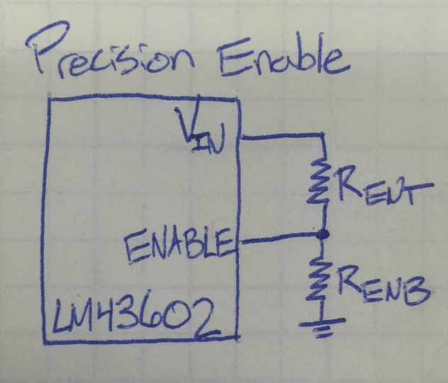
For converters with precision enable, the chip compares the voltage at the enable pin to some set, precise internal voltage reference. Providing an enable voltage above the internal voltage reference turns the converter on, and applying a lower voltage turns the converter off. As shown in Figure 1, you can usually use just a voltage divider from VIN to the enable pin to set a precise enable threshold based on the input supply voltage.
 Figure 1 Simple
Switcher®
LM43602 Enable
Figure 1 Simple
Switcher®
LM43602 EnableHowever, not all regulators have a precision enable function. For converters with logic level EN input, a simple external UVLO circuit can be used to generate the EN signal based on the required VIN range of the converter. The external UVLO circuit provides a logic low signal that keeps the converter disabled until the proper input voltage is reached.
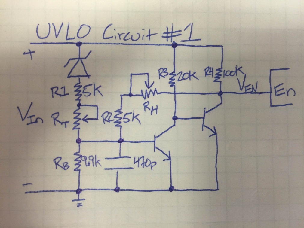
Two simple UVLO schematics can be seen in Figure 2 and Figure 5. The UVLOs were hooked up to the LM22672 step-down converter which was set to produce an output voltage of 5V. The first schematic uses two NPN transistors. Figure 2 shows two potentiometers, RT and RH, used to adjust the UVLO turn-on voltage as well as the hysteresis respectively.
 Figure 2 Simple UVLO Circuit #1
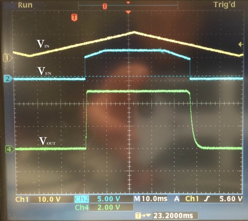
Figure 3 shows the VIN, VEN, and VOUT waveforms of the UVLO and converter from Figure 2.
 Figure 3 UVLO Controlled
Waveforms
Figure 3 UVLO Controlled
WaveformsThe EN voltage comes up when VIN has reached the operating range of the design. The output of the converter is able to produce a consistent 5V when the enable pin is logic high.
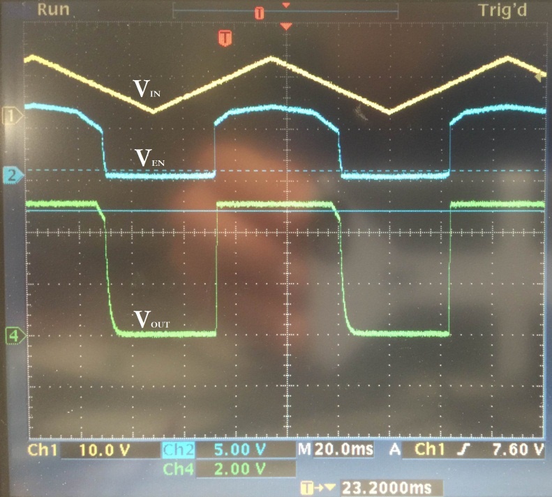
It is always a good idea to have some hysteresis on the turn-on threshold. The hysteresis in this case is set by RH. Figure 4 shows what happens when there is no hysteresis on the UVLO threshold. As the input voltage is hovering around the threshold, the VEN pin can be seen chattering on and off at a high frequency. The enable pin is turning on and off too fast for the converter to start up at all.
 Figure 4 UVLO without
Hysteresis
Figure 4 UVLO without
HysteresisThe second external UVLO circuit uses an NPN and a PNP transistor. In Figure 5, potentiometer RB allows the user to set the VIN UVLO threshold while potentiometer RH sets the hysteresis value.
 Figure 5 Simple UVLO Circuit #2
Figure 6 shows the UVLO successfully enabling and disabling the step-down converter at the set VIN thresholds.
 Figure 6 UVLO Controlled
Waveforms
Figure 6 UVLO Controlled
WaveformsSo, if you find yourself with a converter requiring a logic level enable input and you need a more precise UVLO, take one of the circuits above and adjust the two resistors to set the enable threshold and hysteresis as desired. Simply hook the output of the UVLO circuit up to your IC’s enable pin and you’re good to go!
What's your favorite UVLO circuit? Please feel free to comment below.
Additional Resources
-
Consider TI's SIMPLE SWITCHER LM43602 and LM22672 step-down voltage converters for your next design.
-
Get more information on all of TI’s SIMPLE SWITCHER products.
-
Start a design now with TI’s WEBENCH Power Designer.