SSZTCF6 July 2015 LM1771 , TPS3701 , TPS3847
If you read my last post, ”Why monitoring voltages matters,” you know that monitoring your voltage rails helps you prevent brownouts, sense overvoltage events, gauge your battery level and help you implement an overall diagnostics strategy. This blog will cover how to implement voltage monitoring. There are four key methods:
1. Resistor Divider
This is, perhaps, the simplest approach to voltage monitoring. Dividing down the voltage by a specific factor can be used as a way to prevent under-voltage operation (see Figure 1).
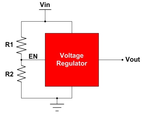 Figure 1 Using a Resistor Divider to
Disable a Voltage Regulator
Figure 1 Using a Resistor Divider to
Disable a Voltage RegulatorThis method is contingent upon the enable characteristics of the monitored integrated circuit (IC). In case the enable voltage range of the IC is wide, it’s not clear what resistor values your resistors should be. Table 1 represents an example. The regulator disables when the voltage applied at the enable pin lies somewhere between 0.4V and 0.9V. With such a wide range, you must design the threshold voltage to be 0.4V to guarantee a disable.
 |
Some devices, like the LM1771, incorporate a “precision enable.” A precision enable narrows the enable and disable voltage range, as shown in Figure 2. This eliminates much of the gray area seen in the previous example and allows the threshold voltage of a resistor divider to be much more precise.
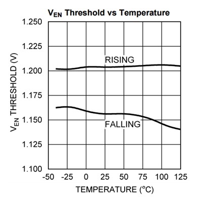 Figure 2 Precision Voltage-enable
Characteristics
Figure 2 Precision Voltage-enable
CharacteristicsThere are a few drawbacks when using a resistor divider though. In addition to the inaccuracies in the enable voltage ranges, a resistor divider provides no hysteresis functionality. As a result, a divided voltage that oscillates around the threshold voltage enables and disables the IC in an undesired fashion.
Resistor values are important with regards to current consumption. The resistor values must be sized small enough to allow for the appropriate amount of current to drive an enable. This situation prohibits sizing the resistors to large enough values where leakage is negligible. Furthermore, the leakage is constant, which can be a problem for a battery-powered system.
Advantages and Disadvantages
- Pros: low cost, simple.
- Cons: no hysteresis, can be inaccurate, constant leakage.
- Bottom line: This technique is a bare-bones approach to voltage monitoring. It is inefficient and may be inaccurate, but accomplishes the basic task of undervoltage protection.
2. Comparator and Reference Voltage
The circuit shown in Figure 3 provides the same basic functionality as a simple reset IC. (The details are expressed succinctly in TI Design reference design TIDP144.) Like a reset IC, it can accurately monitor a voltage and flag the output when it has exceeded a certain threshold. Unlike a reset IC, it requires an external reference and resistors. External components can affect the threshold voltage and hysteresis, as their tolerances must be factored into the operation. (Unlike a reset IC, which incorporates these components monolithically, a discrete solution cannot be trimmed for better accuracy.)
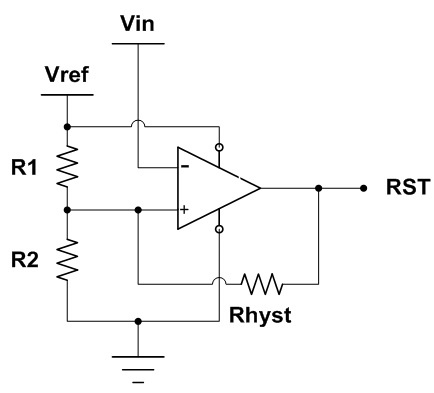 Figure 3 Combining a Comparator with a
Voltage Reference to Detect Voltage
Figure 3 Combining a Comparator with a
Voltage Reference to Detect VoltageAdditionally, it stands to reason that the various external components will grow the overall solution size.
Advantages and Disadvantages
- Pros: simple to design, includes a hysteresis.
- Cons: bigger solution size, can be inaccurate, requires an external voltage reference, constant leakage, resistors required.
- Bottom line: If space or accuracy is not a concern, this is an alternative to a reset IC. The cost may be higher than a reset IC given the number of external components.
3. Onboard Analog-to-digital Converter (ADC)
Many processors come equipped with an ADC that you can dedicate to voltage monitoring. This may seem like an intuitive choice especially when a channel is available. One input/output (I/O) can monitor a voltage rail and another I/O can flag a reset. This method is enticing because the voltage monitoring is effectively “free.”
However, there are two drawbacks. First, the current consumption is much higher. ADCs typically consume ~100µA when active. This can easily dwarf the current consumption of a reset IC by a factor of >100. Second, this approach requires the use of one or two I/Os in addition to the ADC channel. This can be problematic when I/Os or ADC channels are in short supply.
Advantages and Disadvantages
- Pros: “free” voltage monitor, accurate.
- Cons: ADC required, less efficient, uses up I/Os.
- Bottom line: If you are not using an ADC channel and power consumption is not a concern, this type of voltage monitoring is an option. It does use up general-purpose I/Os (GPIOs), however.
4. Reset IC
This monolithic solution optimizes voltage monitoring in terms of power consumption, size and accuracy. It detects undervoltage events and triggers a flag accordingly. Reset ICs like TI’s lowest-power 12V supervisor, the TPS3847, consume only 380nA of supply current, as seen in Figure 4. A reset IC’s small size is also beneficial. The TPS3839 voltage monitor is available in a tiny 1mm-by-1mm small-outline no-lead (SON) package. In order to detect valid undervoltage events, reset ICs require high threshold accuracy. Some devices, like the TPS3701, are 0.75% accurate over temperature.
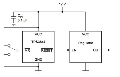 Figure 4 The TPS3847 Monitors a 12-v Rail for an Undervoltage Event
Reset ICs sometimes incorporate other functionality such as overvoltage detection, watchdog timers and battery-backup switchover.
Advantages and Disadvantages
- Pros: small size, low power, simple, accurate, affordable.
- Cons: extra chip versus an on-board ADC.
- Bottom line: This method is the easiest voltage-monitoring solution. It is the most optimized for low power consumption and high accuracy.
I hope that this has been constructive insight into four ways to implement voltage monitoring on your applications, field-programmable gate arrays (FPGAs), digital signal processors (DSPs) and processors. For more information, check out the additional resources on the TI E2E™ Community website in the Supervisors and Reset IC forum.
Additional Resources
- Read my last blog post, “Why monitoring voltages matters.”
- Check out the supervisor reset IC quick reference guide.
- Find application reports on supervisors.
- Review the supervisors overview on TI.com.
- Start simulating your design with SPICE models for these devices: