SSZTCF7 july 2015 ADC083000 , ADS5463
** This is the fourth post in a new RF-sampling blog series that’ll appear monthly on Analog Wire **
Communication system engineers are generally obsessed with signal-integrity issues. They want a low noise system to discern very small signals. They want high linearity performance to maintain immunity to interference. And when discussing high-sampling-rate data converters, their instinct is to sample at a very high speed in order to get many sample points within the period of the signal for best fidelity.
According to the sampling theorem, the minimum sampling rate must be at least twice the largest bandwidth of the signal. Sampling at speeds lower than the minimum results in aliasing. Ugh! This is bad, right? Not necessarily – aliasing can be your friend. Using an undersampling technique, you can use aliasing to your advantage and effectively mix a higher radio frequency (RF) down to a lower frequency captured by an analog-to-digital converter (ADC).
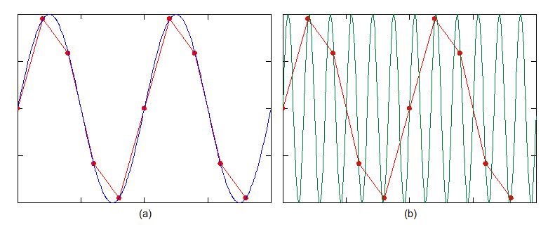
Take a look at the ordinary sinusoid shown in Figure 1a. The blue trace represents the ideal sinusoid signal. The red trace shows the discrete sample points of the ADC. In this example, there are five sample points per period of the signal. With those discrete points, there are actually an infinite number of frequencies that will intersect those exact same points. Figure 1b illustrates a frequency that is six times higher than the original signal yet still intersects the same sample points. The higher frequency will alias down to the ADC’s capture bandwidth. The ADC is acting like a conventional RF mixer in this case. With proper selection of the sampling rate, you can apply this undersampling technique to simplify the receiver architecture.
 Figure 1 (a) Sinusoid Signal with
Discrete Sampling and (b) Visualization of Higher-frequency Aliasing
Figure 1 (a) Sinusoid Signal with
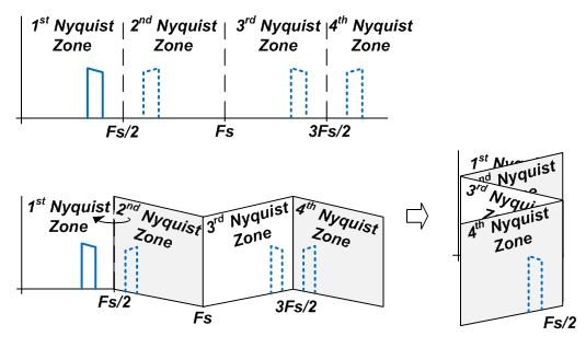
Discrete Sampling and (b) Visualization of Higher-frequency AliasingAnother way to visualize the aliasing picture is to break the spectrum down into separate Nyquist zones. The first Nyquist zone represents the maximum sample bandwidth, which is equal to the sampling rate, Fs, divided by two. The higher Nyquist zones represent the adjacent spectrum bands with equivalent bandwidth. Figure 2 illustrates the Nyquist zone breakout. Visualize the spectrum folding back onto the first Nyquist zone like an accordion. Each signal that ultimately resides in the first Nyquist zone has a counterpart located in a higher Nyquist zone. With proper analog filtering, the ADC can capture a desired signal in one of the higher Nyquist zones, equivalent to a higher RF frequency.
 Figure 2 Nyquist Zones Folding
Back
Figure 2 Nyquist Zones Folding
BackAlthough the sampling theorem states that any higher-frequency component can be aliased down, there is a practical constraint with the ADC’s sample-and-hold circuitry that limits its input bandwidth. The input-bandwidth constraint acts like a filter on the input. As signals exceed the input bandwidth, they will become attenuated to the point where the information is unusable; hence, input bandwidth is an important parameter to investigate when using undersampling.
As an example, the ADC083000 is an 8-bit, 3GSPS ADC with a 3dB input bandwidth of 3GHz. When operating at its maximum sample rate, this device supports signals up through the second Nyquist zone. The ADS5463 is a 12-bit, 500MSPS ADC with an input bandwidth of 2GHz. When operating at its maximum sample rate, this device supports signals up through the eighth Nyquist zone.
Check back for next month’s post, when I will discuss the advantages of cheating physics with oversampling.
Additional Resources
- See how managing input data rates is a breeze in the previous post of this series
- Check out the ADC083000 high speed ADC
- Learn more about TI’s RF sampling ADCs
- See all posts in RJ Hopper’s RF sampling blog series.