SSZTCM7 june 2015
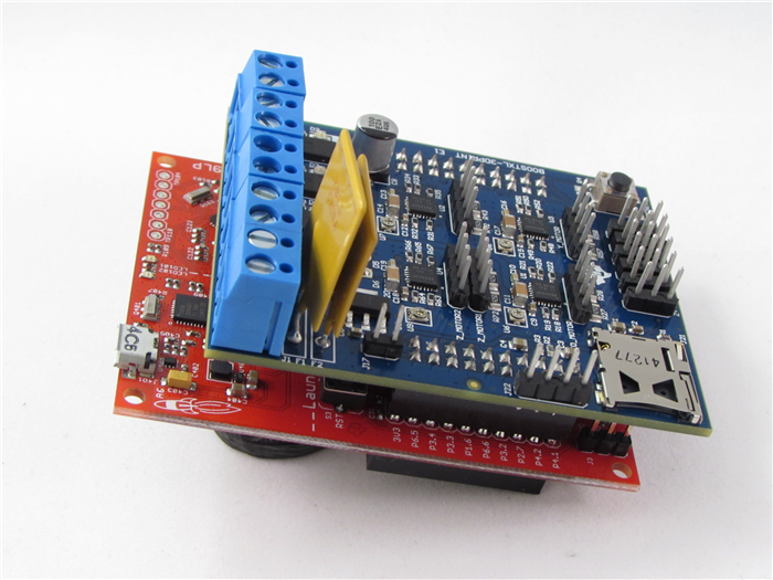
In a previous post, I introduced a TI Design reference design for the 3-D printer controller board TIDA-00405 shown in Figure 1 and gave a brief rundown of some of the key TI devices enabling 3-D printers. Today, I’ll provide more background about 3-D printing in general. This might be old hat to those who are well-versed in 3-D printers, but may turn on a few light bulbs for those new to working with this device.
 Figure 1 TIDA-00405 Reference
Design
Figure 1 TIDA-00405 Reference
Design3-D Printer Controller Design
The first concept to grasp is that 3-D printing comes in many different forms. The all-encompassing term “3-D printing” happens to cover a wide variety of methods. The common thread is that these methods are all “additive manufacturing” techniques. Material is combined together to create an object as opposed to being removed (such as in computer numerical control [CNC] milling or laser cutting). Two of the more prevalent 3-D printing methods are:
- Fused deposition modeling
(FDM). This is the method that people are most familiar with; it’s what
many off-the-shelf printers employ. I often call it the “hot-glue gun approach,”
as the 3-D printer is essentially acting as a very precise hot-glue gun. The
reference design mentioned earlier is based on an
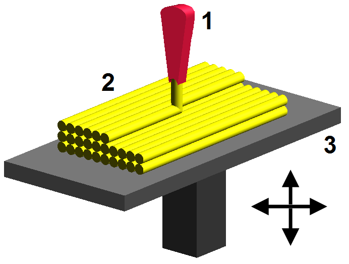
FDM printer, and an example system diagram is available here. In this method (example of how it works shown
in Figure 2), a material (often a thermoplastic) is taken and extruded through a heated
nozzle onto a flat surface, where the material then cools and hardens again. The
nozzle has the ability to move in the X, Y and Z directions, allowing for the
creation of a 3-D object. Many different types of materials are used, but the
most popular are thermoplastics such as acrylonitrile butadiene styrene (ABS)
and polylactic acid (PLA).
 Figure 2 How FDM Printing Works
(Source: Wikimedia.com)
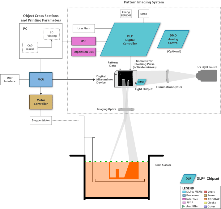
 - Stereolithography (SLA). This method (example system block diagram TIDA-00293shown in Figure 3) creates a 3-D object one layer at a time by curing photoreactive resin with an ultraviolet (UV) light source into the shape of the desired 3-D object. After an XY layer of the resin is cured, an elevator platform will descend to allow the next layer to be processed. This technology generally allows for much finer resolution than FDM methods can achieve, since the UV light can be manipulated more precisely than the mechanical system controlling the FDM nozzle. Texas Instruments has been working hard to enable this type of 3-D printing with DLP® technology, and you can find a TI Design reference design for a DLP stereolithography 3-D printer here.
 Figure 3 TIDA-00293 DLP
Stereolithography System Block Diagram
Figure 3 TIDA-00293 DLP
Stereolithography System Block DiagramNo matter which 3D printing method you use, the first step is to interpret the 3-D object. It all starts with a 3-D model, which is a digital representation of a physical object and can be created or obtained in a variety of methods, including:
- 3-D computer-aided design (CAD) tools. 3-D CAD programs are used in many aspects of engineering; 3-D printing just happens to be one of them. These programs allow you to create a digital 3-D model by hand. This process can be quite tedious and does require some expertise to learn.
- 3-D scanner. Exactly as the name sounds, a 3-D scanner (see Figure 4 for an example scanner) creates a 3-D model of a physical object by scanning the object itself. Imagine something similar to a flat scanner, but instead dealing with 3-D objects.
- 3-D model repositories. Another option is to simply go out and find someone else who has already created the 3-D model. 3-D model libraries are becoming extremely popular, as they contain models for thousands of different objects.
My next post will discuss how a typical FDM 3-D printer turns the 3-D model into something real. If you have any suggestions on what you’d like to see me cover in this series, please log in to post in this blog’s comments section below.