SSZTCO6 may 2015 TMS320F280049C
In the first part of the series, I explained how to use ForceAngle within InstaSPIN-FOC™ to regulate motor start up. Next, I will address generating enough torque during start-up and how to maintain alignment to maximize torque.
Generating Enough Torque
As the starting load is increased, the torque you can generate will be based on the current and the alignment of the fields (determined by the accuracy of the angle estimate).
To insure you can generate enough current, it is imperative that the variable, USER_MOTOR_MAX_CURRENT, be larger than the rated current that is required to generate the rated torque. USER_MOTOR_MAX_CURRRENT is a variable that sets the maximum (positive and negative) output of the speed controller (which is used as the Iq_ref input in the Iq PI current controller in Figure 1).
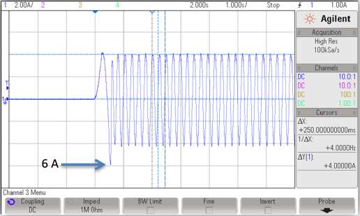
As an example, note the below waveform captured when starting a motor under full load. Producing the torque required to move this rated load requires 4A of current. In this case, the USER_MOTOR_MAX_CURRENT was set to (6.0), and you can see that this 6A current was reached in the first electrical cycle to move the rotor. Then FAST™ was able to provide a valid angle, which allowed the control system to regulate the current usage immediately to only the required 4A.
 Figure 1 Full Load (4A Continuous / 6A
Peak) Start-up
Figure 1 Full Load (4A Continuous / 6A
Peak) Start-upWhen using ForceAngle, even though you are generating a stable feedback angle, it is not necessarily aligned properly to generate maximum torque. You are basically just sweeping a stator field and waiting for the rotor field to lock on and synchronize. When the stator field is not properly oriented, you will not produce enough torque, or in the worst case produce torque in the opposite direction required. To see this in action, you can do some experimenting with ForceAngle and note that sometimes the rotor starts moving perfectly smooth in the correct direction and sometimes it appears to be paused, rocks, or starts moving briefly in the opposite direction. To improve this situation, what is required is a better starting angle for the control system. But how do we do this when FAST can’t provide a valid angle at zero speed?
Alignment
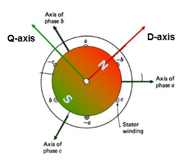
One way to do initial alignment in a field-oriented control system is to inject a DC current into the Id portion of the control system (none into Iq). This is the D-axis, which is defined as the orientation of the rotor flux.
 Figure 2 Field-oriented Control: Orienting Stator Flux (Green) to Rotor Flux (Red) to Maximize Torque Production for a Given Stator Current
If this current is large enough to move the rotor (and any load), this will result in the rotor now being at a known angle (0 radians), meaning that while the forced angle is still emulated, it is at least starting in the proper orientation and in the best position to produce torque. This injection of DC current can be done “manually,” or you can take advantage of the RsRecalibration flag already included in InstaSPIN-FOC. Stator resistance (Rs) identification is part of the motor parameter identification feature and described in the User Guide section 6.5.4. For the initial motor identification, a DC current value (USER_MOTOR_RES_EST_CURRENT) of about 10 to 20 percent of rated is recommended to get a valid value. An RsRecalibration flag is provided so that during run-time operation, this same DC injection can be redone and the Rs value can be measured and updated into the control system. For a heavy load start-up, this DC current value can be increased in an effort to generate enough torque to mechanically align the rotor flux to a known location. It should be noted that increasing this DC current may increase the temperature of the stator windings and should increase the estimated Rs. You should experiment with your application to insure that the estimates from FAST are still valid for the area of operation you will operate the motor after start-up.
Start-up under load testing was one of the items I covered in a recent article for our EDN Spin Cycle blog.
While these methods can dramatically improve the sensorless start-up capabilities for most applications, there are still some limitations, especially in applications that may have highly dynamic loads up to 100 percent of rated torque output. Come back and read part three of this series to find out how to overcome these limitations.