SSZTCT0 april 2023 DRV5013-Q1 , DRV5033-Q1
Systems that have moving mechanical components often have a need to measure something rotating.

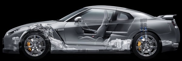
In a car, the speed of the wheels is used for the speedometer, traction control, anti-lock brakes, and cruise control. The engine’s RPM is monitored to control the transmission and stay under the redline. Power windows are often controlled by a small motor with closed-loop rotational sensing. And let’s not forget, when your favorite song comes on, the radio system needs to sense the volume knob as you turn it.
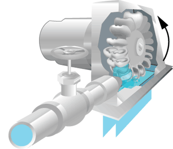
Outside of cars, rotational sensing has many other applications, being used on motor shafts, fans, gears, turbines, and computer mouse wheels. This picture shows an example of using it to measure fluid flow rate:

The name for this type of sensor is rotary encoder. There are two main categories: absolute encoders (which resolve the exact position, in degrees) and incremental encoders (which detect relative change). An easy example of an absolute encoder is a potentiometer.
Within the realm of incremental encoders, the two main types are “speed-only” and “speed and direction”. With the first type, the sensor simply pulses when any rotation occurs, and clockwise versus counter-clockwise are treated the same. The second type adds direction information, and it’s accomplished by adding a second sensor; then the controller in the system considers the order of transitions between the two sensors to know which direction is being turned.
Popular Sensing Methods for Incremental Encoders
3 of the most common technologies for incremental encoders are mechanical, optical, and magnetic.

Mechanical: These are contact-based, where metal brushes on the rotating piece selectively make contact with metal regions on the stator. On the PCB, a voltage can be applied to one terminal, and the presence of voltage can be measured on the toggling terminal as rotation occurs. This is the crudest method, and it comes with several disadvantages:
- Friction on the contacts will make them wear out over time.
- The contacts won’t work well in the presence of contaminants like dirt and corrosion.
- Bandwidth (detections per second) is greatly limited by the debouncing time of the brushes, which can be milliseconds.
- The mechanical design and assembly process can be somewhat complex.

Optical: These typically involve a disk with holes cut out (a mask), an LED on one side, and two photodetectors on the other. Optical encoders can achieve the highest resolution of any encoder type, with thousands of pulses per revolution, but with that comes stringent manufacturing and alignment tolerances. Applications range all the way from computer mouse wheels to high-end semiconductor photolithography equipment. The general weakness is its lack of robustness in harsh industrial environments, since any physical contaminate will block light, and vibration can be a problem. Also, at high temperatures the LED’s lifetime will diminish.

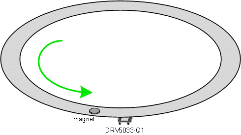
Magnetic: A 3-pin Hall Effect IC matched with a small magnet on the rotating piece is a surprisingly simple and robust way to measure speed. The DRV5033-Q1 is suitable for this. The sensor can be fully enclosed and isolated from the environment, and the magnetic field from the magnet passes a distance, ignoring most types of contaminates in between.

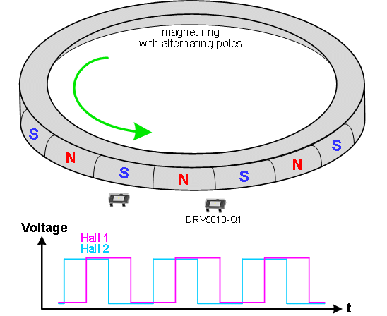
To measure speed and direction magnetically, the standard solution is to use two Hall latch-type sensors and a magnet shaped in a ring with alternating north and south poles. For example, the DRV5013-Q1 and a magnet like this. As this next picture shows, when each sensor is close to a South pole, it outputs Low, and North poles cause a High output. The two sensors produce what’s called a quadrature output, a fancy name for signals 90° out of phase.

For any given 2-bit state, there’s a unique 2-bit state for a clockwise increment, and another unique 2-bit state for a counter-clockwise increment. So the microcontroller firmware is quite simple.
TI has made a reference design for this, TIDA-00480, and you can check out this whiteboard video on Youtube.
The benefits of TI’s Hall encoder solution include:
- Extremely simple to design, and no configuration
- Highly cost competitive
- Zero wear-and-tear and robust in harsh environments, with >10 year lifetime
- The sensing and signaling are digital, giving noise immunity
- High-performance: bandwidth is >20kHz, and response time is 15µs
- AEC-Q100 automotive qualified for up to 175°C junction
Thanks for reading! Comments are welcome.