SWCU192 November 2021 CC1312R7 , CC1352P7 , CC2652P7 , CC2652R7
20.3.2.6 Math Accelerator (MAC)
The Sensor Controller can leverage the MAC module for mathematical operations, such as:
- 16-bit signed or unsigned multiplication with optional accumulation of the result
- 16-bit or 32-bit signed or unsigned addition of programmable term and accumulator
The results from these operations are always stored in the 40-bit signed accumulator. The Sensor Controller can perform the following operations directly on the accumulator:
- Initialize the accumulator
- Reset the accumulator
- Read arbitrary 16-bit slice of the accumulator
- Read the number of leading sign or zero bits in the accumulator
- Perform logical shifts and arithmetic right-shift of the accumulator
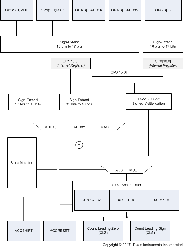
Figure 20-7 shows a block diagram of the MAC.
For consistent timing, it is important that the Sensor Controller and the MAC operational rates are equal. Hence, the Sensor Controller application must set the MAC_OP_RATE bit of the AUX_SYSIF:PEROPRATE register to SCE_RATE (see Section 20.8.9).
Though not the primary use case, the System CPU can also use the MAC. To achieve consistent timing in this case, the application must set the MAC_OP_RATE bit of the AUX_SYSIF:PEROPRATE register to BUS_RATE (see Section 20.8.9).
 Figure 20-7 MAC Block Diagram
The result of addition and multiplication operations is still valid if operations are unequal, but the time to complete the operations can vary.
The addition and multiplication operations require multiple peripheral clock cycles to complete. Consider the following assembly example that was generated from the Sensor Controller Studio.
# Sample assembly (Example code produced by the Sensor Controller Studio)
# The contents of r4 are assumed to be signed in this example
0: out     R4,[#IOP_MAC_OP1SADD16]   ; add r4 to the accumulator
1: in      R1,[#IOP_MAC_15_0]        ; Store result bits 15:0 in r1
2: out     R4,[#IOP_MAC_OP1SMUL]     ; Multiply r4 with operand 0(assumed pre-programmed)
3: in      R2,[#IOP_MAC_31_16]       ; Store result bits 31:16 in r2
4: in      R3,[#IOP_MAC_15_0]        ; Store result bits 15:0  in r3
# The Sensor Controller uses the alias I/O memory space
IOP_MAC_OP1SMUL                equ 11
IOP_MAC_OP1SADD16              equ 15
IOP_MAC_31_16                  equ 24
IOP_MAC_15_0                   equ 23
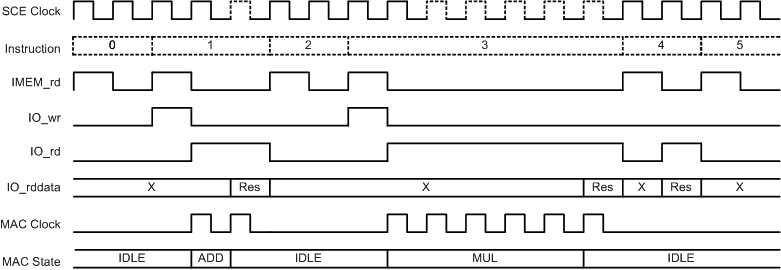
As shown in Figure 20-8, the addition operation requires one peripheral clock cycle to complete. Because the Sensor Controller attempts to read the result of the operation immediately after triggering it, the Sensor Controller stalls for one clock cycle. This condition gates the clock to the Sensor Controller until the result is ready.
Figure 20-8 also shows that the multiplication operation requires five peripheral clock cycles to complete. As the Sensor Controller tries to read the result of the operation immediately after triggering it, the Sensor Controller stalls for five clock cycles. The clock to the Sensor Controller becomes clock gated until the result is ready. The multiply-accumulate operation requires the same number of peripheral clock cycles to complete.
 Figure 20-8 MAC Timing Diagram