SWCU192 November 2021 CC1312R7 , CC1352P7 , CC2652P7 , CC2652R7
20.1.1 AUX Block Diagram
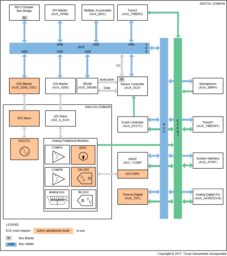
Figure 20-1 shows connections for the modules in the AUX domain.
 Figure 20-1 AUX Domain Block Diagram
Figure 20-1 shows that there are two bus masters in the AUX domain, the Sensor Controller and MCU domain Bus Bridge. The System CPU and the µDMA access the AUX domain over the bus bridge. Bus arbitration between the Sensor Controller and the MCU domain Bus Bridge happens upon access of modules that are connected to the same bus arbiter. The bus arbiter always prioritizes the Sensor Controller. Hence, the System CPU can access the oscillator interface while the Sensor Controller accesses the SPI master without interfering with the other.