SWRA578B October 2017 – April 2020 CC1312PSIP , CC1312R , CC1314R10 , CC1352P , CC1352P7 , CC1352R , CC2620 , CC2630 , CC2640 , CC2640R2F-Q1 , CC2642R , CC2642R-Q1 , CC2650MODA , CC2652P , CC2652R , CC2652R7 , CC2652RB , CC2652RSIP
3.1.3 LC Flow Meter
The LC flow meter example uses a pair of capacitors and inductors to keep track of the position of a spinning disc to measure the flow volume of a fluid or gas. The disc is half metal and half non-metal. The LC sensor is able to detect if there is a metal piece in close proximity, so with two sensors the rotation of the disc can be tracked. The BOOSTXL-ULPSENSE also includes trigger circuits to make the pulses going in to the Sensor controller narrower, which enables even lower current consumption.
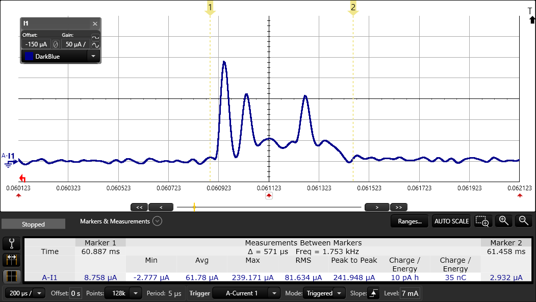
The LC Flow Meter example works by creating a oscillation in the LC sensor on the BOOSTXL-ULPSENSE. The dampening of the oscillation depends on the capacitance in the system, and when a metal disc is present the dampening is increased. The pulse counter peripheral is used to count the oscillations on the COMPA input, before the amplitude is below the Reference DAC level.
The LC flow meter example is tested with a metal piece over the inductors, emulating a real flowmeter application. When measuring, the metal piece is placed so it covers only one inductor. When the Sensor controller detects flow, it will notify the System CPU. The System CPU will blink one of the two LEDs depending on which direction the metal piece spins.
| Average Current Consumption | Unit | |
|---|---|---|
| Flow Meter 100 Hz | 5.9 | µA |
A separate test with the flow meter running at 16 Hz instead of the normal 100 Hz was also tested. To create this example, the variable “execInterval” in Sensor Controller Studio is changed from 40 to 250.
| Average Current Consumption | Unit | |
|---|---|---|
| Flow Meter 16 Hz | 1.7 | µA |
 Figure 8. LC Flowmeter: One Measurement