SWRA696A April 2021 – November 2021 CC1352P , CC1352P7 , CC1352R
4 Setting Up WB-DSSS in SmartRF Studio
The SmartRF studio contains the settings for the optimized WB-DSSS cases that can be tested from within the GUI. By launching the GUI and connecting CC13x2 launchpads with USB cable, the devices will show up in the GUI’s console. From there, by clicking each one from the list of connected devices, the LaunchPads can be independently configured for TX and RX and a RF link test can be conducted.
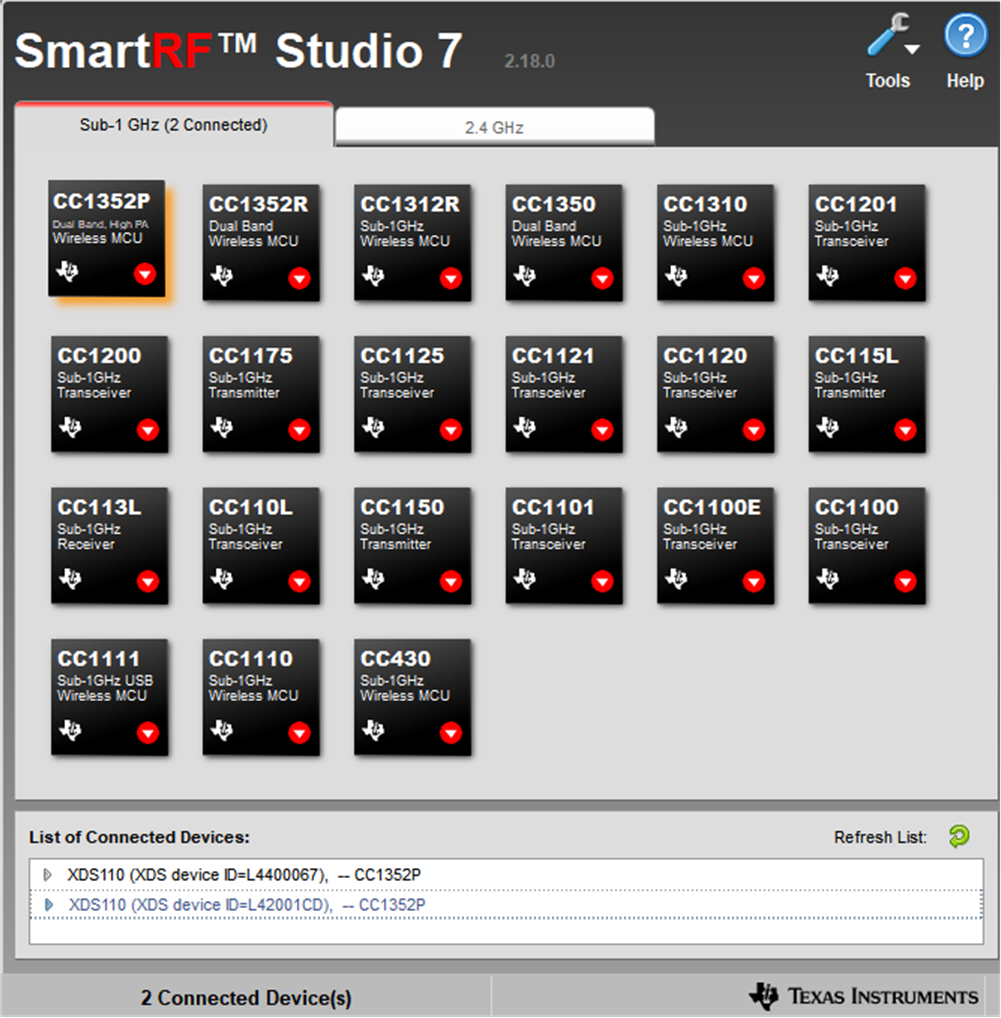 Figure 4-1 SmartRF GUI Showing Two
CC1352P in List of Connected Devices
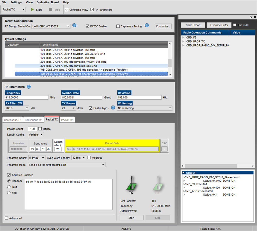 Figure 4-2 SmartRF Studio Showing WB-DSSS
Setup in Transmit Mode
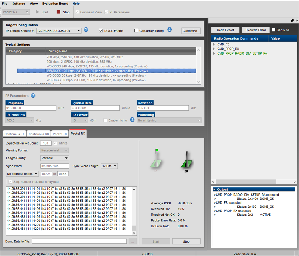 Figure 4-3 SmartRF Studio Showing WB-DSSS
Setup in Receive Mode
Figure 4-3 SmartRF Studio Showing WB-DSSS
Setup in Receive ModePer default, the WB-DSSS settings in the SmartRF use formatConf.fecMode = 0x0. With this setting, the user can define the first 32-bits of the sync word. The patch will then append this to the remaining 32-bits of the sync word. For example, if syncWord = 0x12345678, the overall sync word will become 0x12345678_3CC3CCCC. The SmartRF studio setup for testing this scenario is shown in Figure 4-2 and Figure 4-3.
Alternatively, the WB-DSSS settings in SmartRF Studio can be changed by setting formatConf.fecMode = 0x8 and formatConf.whitenMode = 0x1. In this mode, the MCE patch overrides any user defined sync word and replaces it with 0x333C_3C33_3CC3_CCCC. This is also compatible with default modes for CC13x0 devices. Note the settings in Figure 4-4.
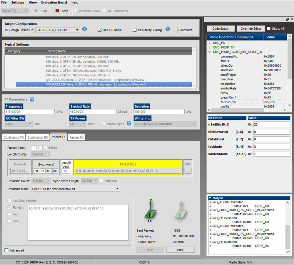 Figure 4-4 SmartRF Studio Showing WB-DSSS
Setup in Transmit Mode (note the setup of sync word when testing in SmartRF
Studio)
 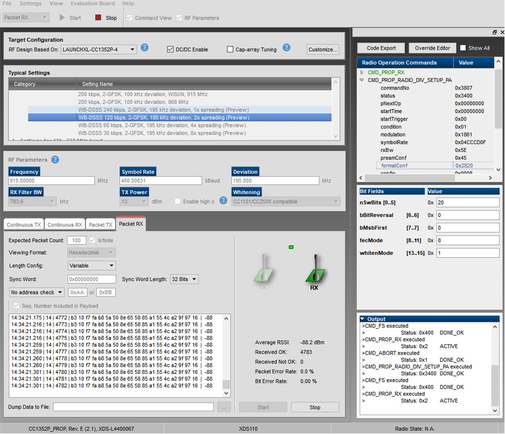 Figure 4-5 SmartRF Studio Showing WB-DSSS
Setup in Receive Mode (note the setup of sync word when testing in SmartRF
Studio)