SWRA725 November 2021 AWR2944
2 Crossing Interference
Crossing interference can only happen if the victim radar and the aggressor radar have chirp designs with different slopes. In such a case, the two chirps can cross each other. When the crossing happens, the victim will observe a transient interference event. The aggressor’s transmitted chirp is mixed with victim’s chirp and downconverted. The energy of the aggressor is observable to the victim only if their frequency difference falls into victim’s IF bandwidth. If the frequency difference is greater, then most of the energy will be filtered out by analog and digital filters. As most of the FMCW radars encountered in the field will have different slopes, and chirp repeat rates, crossing interference is the most likely interference that an FMCW radar will have to face.
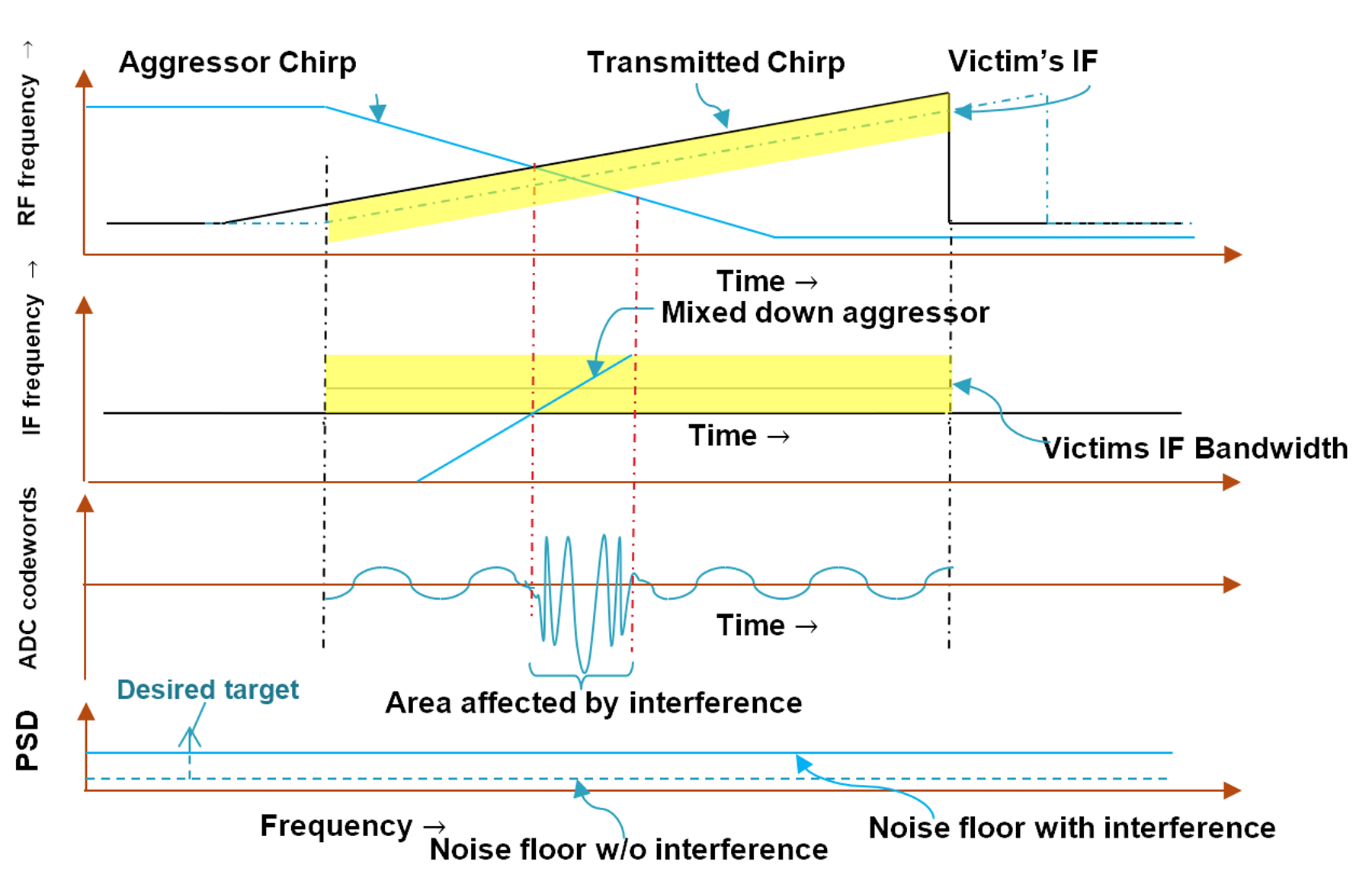
An example is given in Figure 2-1. As the aggressor's chirp crosses the victim’s transmitted chirp (top plot), the aggressor chirp's energy is observed as a chirp that rapidly moves through the IF bandwidth (second plot). In time domain, the region affected by interference thus resembles a glitch (third plot).
 Figure 2-1 Crossing Interference Causing
a Glitch in the Time Domain Signal
Figure 2-1 Crossing Interference Causing
a Glitch in the Time Domain SignalFinally, after a Fourier transform is applied on the ADC samples, in the frequency domain, these crossing interferers typically increase the noise floor and reduce the SNR of strong targets and bury weak targets, thereby affecting detection and creating momentary blind spots. The glitch duration (τGlitch) is governed by the victim’s IF bandwidth and the slopes of the victim (slopevictim) and the aggressor (slopeaggressor). It is shown in Equation 1:
Note that the glitch duration is typically small. For example, if the IF bandwidth is 12 MHz and the difference in slopes is 40 MHz/μs, approximately 0.3 μs, or four samples of the final ADC output, would be affected by interference.