SWRA726 March 2022 CC1120 , CC1121 , CC1201 , CC1310 , CC1311P3 , CC1311R3 , CC1312PSIP , CC1312R , CC1312R7 , CC1314R10 , CC1350 , CC1352P , CC1352R , CC1354P10 , CC1354R10 , CC2340R5-Q1 , CC2640R2L , CC2651R3 , CC2652P , CC2652P7 , CC2652R , CC2652R7 , CC2652RB , CC2652RSIP , CC3130 , CC3135MOD , CC3230S , CC3235MODAS , CC3235MODASF , CC3235MODSF , CC3235S , WL1801MOD , WL1805MOD , WL1807MOD , WL1831 , WL1831MOD , WL1835MOD , WL1837MOD
- Trademarks
- 1Introduction
- 2Antenna Standing Wave Ratio (SWR) Measurement
- 3Evaluation Board Matching Components Location
- 4Volpert-Smith Chart
- 5868-MHz PCB Helix Antenna Measurement and Matching
- 62.4-GHz PCB Compact Antenna Measurement and Matching
- 7 2.4-GHz PCB Inverted-F Antenna Measurement and Matching
- 8Fast in-circuit or in-device Antenna Verification
- 9Conclusion
6 2.4-GHz PCB Compact Antenna Measurement and Matching
Antenna matching described in this chapter is showing an example of cased 2.4-GHz PCB compact (15 mm by 6 mm) antenna (Figure 6-1). This antenna is popular for portable devices with space constrained boards as it has small geometrical sizes. Detailed antenna description can be found on document AN043.
 Figure 6-1 Compact 2.4 GHz PCB
Antenna
Figure 6-1 Compact 2.4 GHz PCB
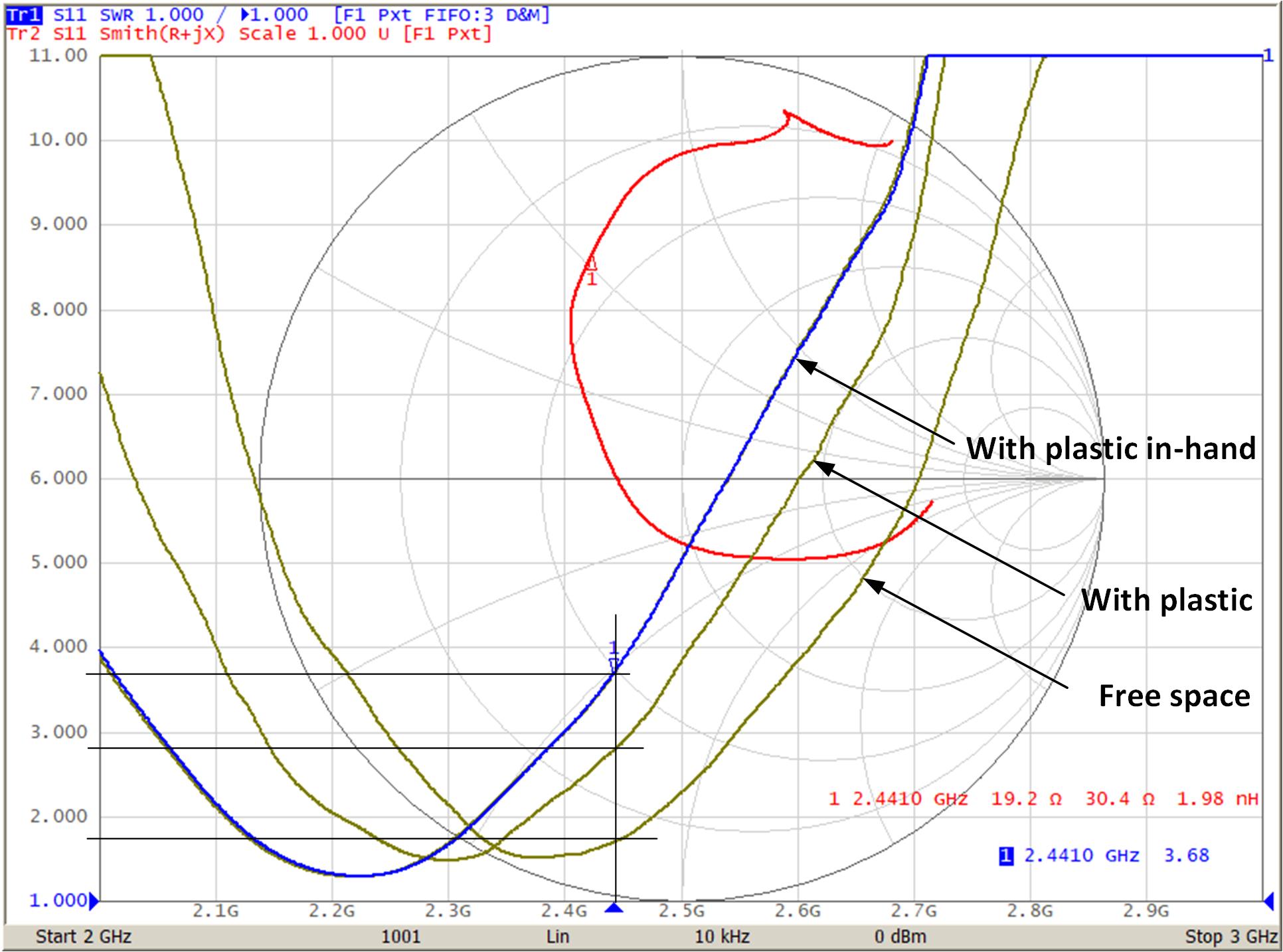
AntennaPortable devices are usually made for in-hand operation. Plastic case and human’s body can detune the antenna. In such case, a final matching should be done including the case and human’s body, representing a real device’s operation condition. Figure 6-2 is showing measured SWR values in free space, in a plastic case and in the plastic case with in-hand placement.
 Figure 6-2 Measured SWR Levels
Users can see the SWR value changes from 1:1.70 (in free space) up to 1:3.68 when antenna is cased and placed in hand.
For given impedance of 19.2 + j30.4 Ohm (at 2.4410 GHz) Smith calculator shows ideal components values for matching network 4-4A of 1.9 pF plus 3.5 nH.
It’s important to remember, the calculator gives the ideal values. But for matching job, especially with human’s body affecting the antenna, the final matching circuit can be different.
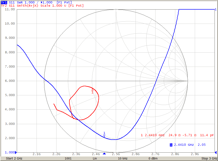
For matching job, the only capacitor of 1.8 pF installed. Measured impedance with plastic and in-hand placement shown on Figure 6-3.
 Figure 6-3 Measured Impedance with 1.8 pF
Capacitor Installed
Figure 6-3 Measured Impedance with 1.8 pF
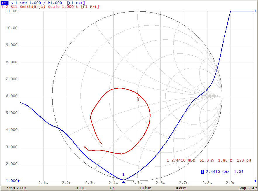
Capacitor InstalledLooking at measured marker 1 and Smith calculator’s chart gives an idea that parasitic capacitance is about 0.5 pF. This means the value can be adjust down to about 1.2 pF. Figure 6-4 shows measured impedance with 1.5 pF installed.
 Figure 6-4 Measured Impedance with 1.5 pF
Capacitor Installed
Figure 6-4 Measured Impedance with 1.5 pF
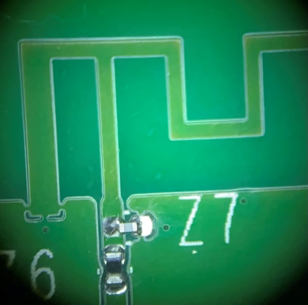
Capacitor InstalledFor this matching job even doesn’t necessary to install the inductor and it can be replaced by SMD jumper (Figure 6-5) as SWR value is 1:1.05.
 Figure 6-5 Board with Installed Final
Matching Components