SWRA726 March 2022 CC1120 , CC1121 , CC1201 , CC1310 , CC1311P3 , CC1311R3 , CC1312PSIP , CC1312R , CC1312R7 , CC1314R10 , CC1350 , CC1352P , CC1352R , CC1354P10 , CC1354R10 , CC2340R5-Q1 , CC2640R2L , CC2651R3 , CC2652P , CC2652P7 , CC2652R , CC2652R7 , CC2652RB , CC2652RSIP , CC3130 , CC3135MOD , CC3230S , CC3235MODAS , CC3235MODASF , CC3235MODSF , CC3235S , WL1801MOD , WL1805MOD , WL1807MOD , WL1831 , WL1831MOD , WL1835MOD , WL1837MOD
- Trademarks
- 1Introduction
- 2Antenna Standing Wave Ratio (SWR) Measurement
- 3Evaluation Board Matching Components Location
- 4Volpert-Smith Chart
- 5868-MHz PCB Helix Antenna Measurement and Matching
- 62.4-GHz PCB Compact Antenna Measurement and Matching
- 7 2.4-GHz PCB Inverted-F Antenna Measurement and Matching
- 8Fast in-circuit or in-device Antenna Verification
- 9Conclusion
1 Introduction
As operational frequency increases, parameters of lines, circuits, and traces on PCB will play a critical role, because geometrical sizes become comparable with wavelength. Geometrical sizes help users determine their physical sizes (length and width). As an example, waves lengths from 433 MHz to 5.5 GHz (Table 1-1).
| Frequency, MHz | Wave length, λ, cm | Wave length, λ/4, cm |
|---|---|---|
| 433 | 69.23 | 17.30 |
| 868 | 34.53 | 8.63 |
| 2440 | 12.29 | 3.07 |
| 5500 | 5.45 | 1.36 |
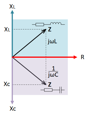
Lines and traces change their operational behavior while operational frequency increases and have not only an active resistance. Depending on frequency, inductive or capacitive reactance can be dominant and their values varies. For high frequencies, use the impedance or “Z” (meaning active with reactive resistances). Resistance (R) doesn’t change with the frequency, but reactance (±jX) does change. This means the impedance (Z) varies by frequency.
 Figure 1-1 Graphical Representation of Impedance (Z)