SWRA759
November 2022
Abstract
Trademarks
1
Introduction
2
Hardware BOM and Firmware Modification
3
Firmware Compiler Environment Setup (if change or evaluate code are needed)
3.1
Hardware and Software Prepared
3.2
Hardware Connection
3.3
CCS Environment Configuration
4
Upgrade Firmware of CC3235 and OA7000
4.1
Prepared Components
4.2
Upgrade CC3235 Firmware
4.3
Upgrade OA7000 Firmware
5
How to Test Current and Startup Time
5.1
Prepared Components
5.2
Setup Test Environment
5.3
Start Testing
3.2
Hardware Connection
Short J11.3 and J11.4 with a jumper in order to enable download function via UART.
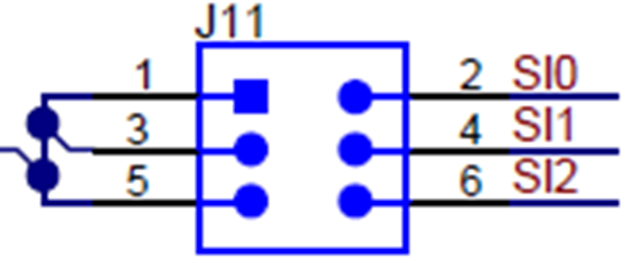
Figure 3-1
J11 Connector
Connect J13 to CC3235EVM board UART pin according to the
Connections Between CC32xx LaunchPad™ and Wireless Camera Module (J13 Connector)
figure in the
Design Guide: TIDA-010224 Low-Power Wireless Camera Reference Design for Extended Battery Life
.
Connect J5 to CC3235EVM board’s J7(XDS10 OUT) connector with a JTAG cable.
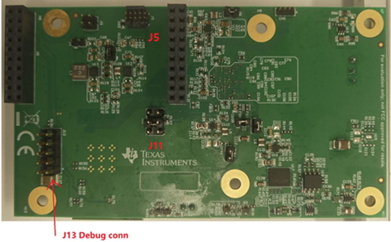
Figure 3-2
PCB Connector
Connect the PC to the camera board and the CC3235EVM board with the 2x USB cable. Power on these two boards.
千亿体育app官网登录(中国)官方网站IOS/安卓通用版/手机APP
|
米乐app下载官网(中国)|ios|Android/通用版APP最新版
|
米乐|米乐·M6(中国大陆)官方网站
|
千亿体育登陆地址
|
华体会体育(中国)HTH·官方网站
|
千赢qy国际_全站最新版千赢qy国际V6.2.14安卓/IOS下载
|
18新利网v1.2.5|中国官方网站
|
bob电竞真人(中国官网)安卓/ios苹果/电脑版【1.97.95版下载】
|
千亿体育app官方下载(中国)官方网站IOS/安卓/手机APP下载安装
|