SWRU271I October   2010  – January 2020 CC2540 , CC2540T , CC2541 , CC2541-Q1 , CC2640R2F


  1.   Preface
    1.     Trademarks
    2.     Related Documentation
  2. 1Overview
    1. 1.1 Support Note
    2. 1.2 Introduction
    3. 1.3 Bluetooth Low Energy Protocol Stack Basics
  3. 2The TI Bluetooth Low Energy Software Development Platform
    1. 2.1 Overview
    2. 2.2 Configurations
    3. 2.3 Projects
    4. 2.4 Software Overview
  4. 3The Operating System Abstraction Layer (OSAL)
    1. 3.1 Overview
    2. 3.2 Task Initialization
    3. 3.3 Task Events and Event Processing
    4. 3.4 Heap Manager
    5. 3.5 OSAL Messages
  5. 4The Application and Profiles
    1. 4.1 Overview
    2. 4.2 Project Overview
    3. 4.3 Start-up in main()
    4. 4.4 Application Initialization
    5. 4.5 Event Processing
      1. 4.5.1 Periodic Event
      2. 4.5.2 OSAL Messages
    6. 4.6 Callbacks
    7. 4.7 Complete Attribute Table
    8. 4.8 Additional Sample Projects
  6. 5The Bluetooth Low Energy Protocol Stack
    1. 5.1 Overview
    2. 5.2 Generic Access Profile (GAP)
      1. 5.2.1 Overview
        1. 5.2.1.1 Connection Parameters
        2. 5.2.1.2 Effective Connection Interval
        3. 5.2.1.3 Connection Parameter Considerations
        4. 5.2.1.4 Connection Parameter Update
        5. 5.2.1.5 Connection Termination
      2. 5.2.2 GAP Abstraction
      3. 5.2.3 Configuring the GAP Layer
    3. 5.3 GAPRole Task
      1. 5.3.1 Peripheral Role
      2. 5.3.2 Central Role
    4. 5.4 Gap Bond Manager (GAPBondMgr)
      1. 5.4.1 Overview of Bluetooth Low Energy Security
      2. 5.4.2 Using the GapBondMgr Profile
      3. 5.4.3 GAPBondMgr Examples for Various Security Modes
        1. 5.4.3.1 Pairing Disabled
        2. 5.4.3.2 Just Works Pairing Without Bonding
        3. 5.4.3.3 Just Works Pairing With Bonding Enabled
        4. 5.4.3.4 Authenticated Pairing
        5. 5.4.3.5 Authenticated Pairing With Bonding Enabled
    5. 5.5 Generic Attribute Profile (GATT)
      1. 5.5.1 GATT Characteristics and Attributes
      2. 5.5.2 GATT Services and Profile
      3. 5.5.3 GATT Client Abstraction
        1. 5.5.3.1 Using the GATT Layer Directly
      4. 5.5.4 GATT Server Abstraction
        1. 5.5.4.1 GATTServApp Module
          1. 5.5.4.1.1 Building Up the Attribute Table
        2. 5.5.4.2 Profile Architecture
          1. 5.5.4.2.1 Attribute Table Definition
            1. 5.5.4.2.1.1 Service Declaration
            2. 5.5.4.2.1.2 Characteristic Declaration
            3. 5.5.4.2.1.3 Characteristic Value
            4. 5.5.4.2.1.4 Client Characteristic Configuration
          2. 5.5.4.2.2 Add Service Function
          3. 5.5.4.2.3 Register Application Callback Function
          4. 5.5.4.2.4 Read and Write Callback Functions
            1. 5.5.4.2.4.1 Read Request from A GATT Client
            2. 5.5.4.2.4.2 Write Request From Client
          5. 5.5.4.2.5 Get and Set Functions
    6. 5.6 L2CAP
    7. 5.7 HCI
      1. 5.7.1 HCI Extension Vendor-Specific Commands
      2. 5.7.2 Receiving HCI Extension Events in the Application
    8. 5.8 Library Files
  7. 6Drivers
    1. 6.1  Overview
    2. 6.2  ADC
    3. 6.3  AES
    4. 6.4  LCD
    5. 6.5  LED
    6. 6.6  KEY
    7. 6.7  DMA
    8. 6.8  UART and SPI
    9. 6.9  Other Peripherals
    10. 6.10 Simple NV (SNV)
  8. 7Creating a Custom Bluetooth Low Energy Application
    1. 7.1 Overview
    2. 7.2 Configuring the Bluetooth Low Energy Stack
    3. 7.3 Define Bluetooth Low Energy Behavior
    4. 7.4 Define Application Tasks
    5. 7.5 Configure Hardware Peripherals
    6. 7.6 Configuring Parameters for Custom Hardware
      1. 7.6.1 Board File
      2. 7.6.2 Adjusting for 32-MHz Crystal Stabilization Time
      3. 7.6.3 Setting the Sleep Clock Accuracy
    7. 7.7 Software Considerations
      1. 7.7.1 Memory Management for GATT Notifications and Indications
      2. 7.7.2 Limit Application Processing During Bluetooth Low Energy Activity
      3. 7.7.3 Global Interrupts
  9. 8Development and Debugging
    1. 8.1 Overview
    2. 8.2 IAR Overview
    3. 8.3 Using IAR Embedded Workbench
      1. 8.3.1 Open an Existing Project
      2. 8.3.2 Project Options, Configurations, and Defined Symbols
      3. 8.3.3 Building and Debugging a Project
      4. 8.3.4 Linker Map File
  10. 9General Information
    1. 9.1 Overview
    2. 9.2 Porting From BLE-Stack 1.5.0 to 1.5.1
    3. 9.3 Porting From BLE-Stack 1.4.2 to 1.5.0
    4. 9.4 Porting From Earlier BLE-Stack Versions
      1. 9.4.1 Porting BLEv1.4.1 Projects to BLEv1.4.2
      2. 9.4.2 Porting BLEv1.4.0 Projects to BLEv1.4.1
        1. 9.4.2.1 Project Porting Directions
        2. 9.4.2.2 API Changes
        3. 9.4.2.3 Typedef Changes
        4. 9.4.2.4 Structure Changes
          1. 9.4.2.4.1 Array Elements Changed to Pointers
          2. 9.4.2.4.2 Additional Fields in Key Distribution Strucutre
        5. 9.4.2.5 Default Value of HAL Components
        6. 9.4.2.6 Allocating Memory for Over-the-Air Messages
        7. 9.4.2.7 Allocation of Client Characteristic Configuration Table
      3. 9.4.3 Porting BLEv1.3.2 Projects to BLEv1.4.0
      4. 9.4.4 Porting BLEv1.2 Projects to BLEv1.3
      5. 9.4.5 Porting From CC2540 to CC2541 Project
    5. 9.5 Release Notes History
    6. 9.6 Document History
  11.   A GAP API
    1.     A.1 Commands
    2.     A.2 Configurable Parameters
    3.     A.3 Events
  12.   B GAPRole Peripheral Role API
    1.     B.1 Commands
    2.     B.2 Configurable Parameters
    3.     B.3 Callbacks
      1.      B.3.1 State Change Callback (pfnStateChange)
      2.      B.3.2 RSSI Callback (pfnRssiRead)
  13.   C GAPRole Central Role API
    1.     C.1 Commands
    2.     C.2 Configurable Parameters
    3.     C.3 Callbacks
      1.      C.3.1 RSSI Callback (rssiCB)
      2.      C.3.2 Central Event Callback (eventCB)
  14.   D GATT/ATT API
    1.     D.1 Overview
    2.     D.2 Server Commands
    3.     D.3 Client Commands
    4.     D.4 Return Values
    5.     D.5 Events
    6.     D.6 GATT Commands and Corresponding ATT Events
    7.     D.7 ATT_ERROR_RSP Error Codes
  15.   E GATTServApp API
    1.     E.1 Overview
    2.     E.2 Commands
  16.   F GAPBondMgr API
    1.     F.1 Overview
    2.     F.2 Commands
    3.     F.3 Configurable Parameters
    4.     F.4 Callbacks
      1.      F.4.1 Passcode Callback (passcodeCB)
      2.      F.4.2 Pairing State Callback (pairStateCB)
  17.   G HCI Extension API
    1.     G.1 Overview
    2.     G.2 Commands
    3.     G.3 Host Error Codes
  18.   Revision History

Linker Map File

After building a project, IAR generates a linker map file that you can find in the Output group in the file list.
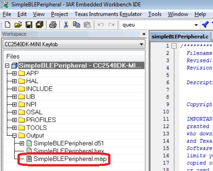
figure_29_swru271.gifFigure 8-11 Map File in File List

The map file contains low-level information about the build. Lines of text similar to the following are at the end of the map file:

118 544 bytes of CODE memory 35 bytes of DATA memory (+ 73 absolute ) 6 242 bytes of XDATA memory 194 bytes of IDATA memory 8 bits of BIT memory 4 149 bytes of CONST memory Errors: none Warnings: none

This text shows the total code space (CODE memory) and RAM (XDATA memory) the project uses. Ensure the sum of the CODE memory plus CONST memory does not exceed the maximum flash size of the device (either 128KB or 256KB, depending on the version of the CC2540/41). Ensure the size of the XDATA memory does not exceed 7936 bytes, as the CC2540/41 contains 8KB of SRAM (256 bytes are reserved).

For more specific information, the map file contains a section called MODULE SUMMARY. This section is approximately 200 to 300 lines before the end of the file (the exact location varies from build-to-build). Within this section, you can see the exact amount of flash and memory for every module in the project.