SWRU439M October 2015 – April 2022
- Trademarks
- 1Introduction
- 2Overview
- 3Prerequisites
- 4Installation
- 5Sensor Controller Studio Tutorials
-
6Sensor Controller Studio Walkthrough
- 6.1 Start Page and Navigation
- 6.2 Documentation
- 6.3 Open the Example
- 6.4 Project Panel
- 6.5 Task Panel Settings
- 6.6 Constants and Data Structures Panel
- 6.7 Task Code Editor Panels
- 6.8 I/O Mapping Panel
- 6.9 Code Generator Panel
- 6.10 Compiling Example Applications in IAR or CCS
- 6.11 Task Testing Panel
- 6.12 Run-Time Logging Panel
- 7References
- 8Revision History
6.4 Project Panel
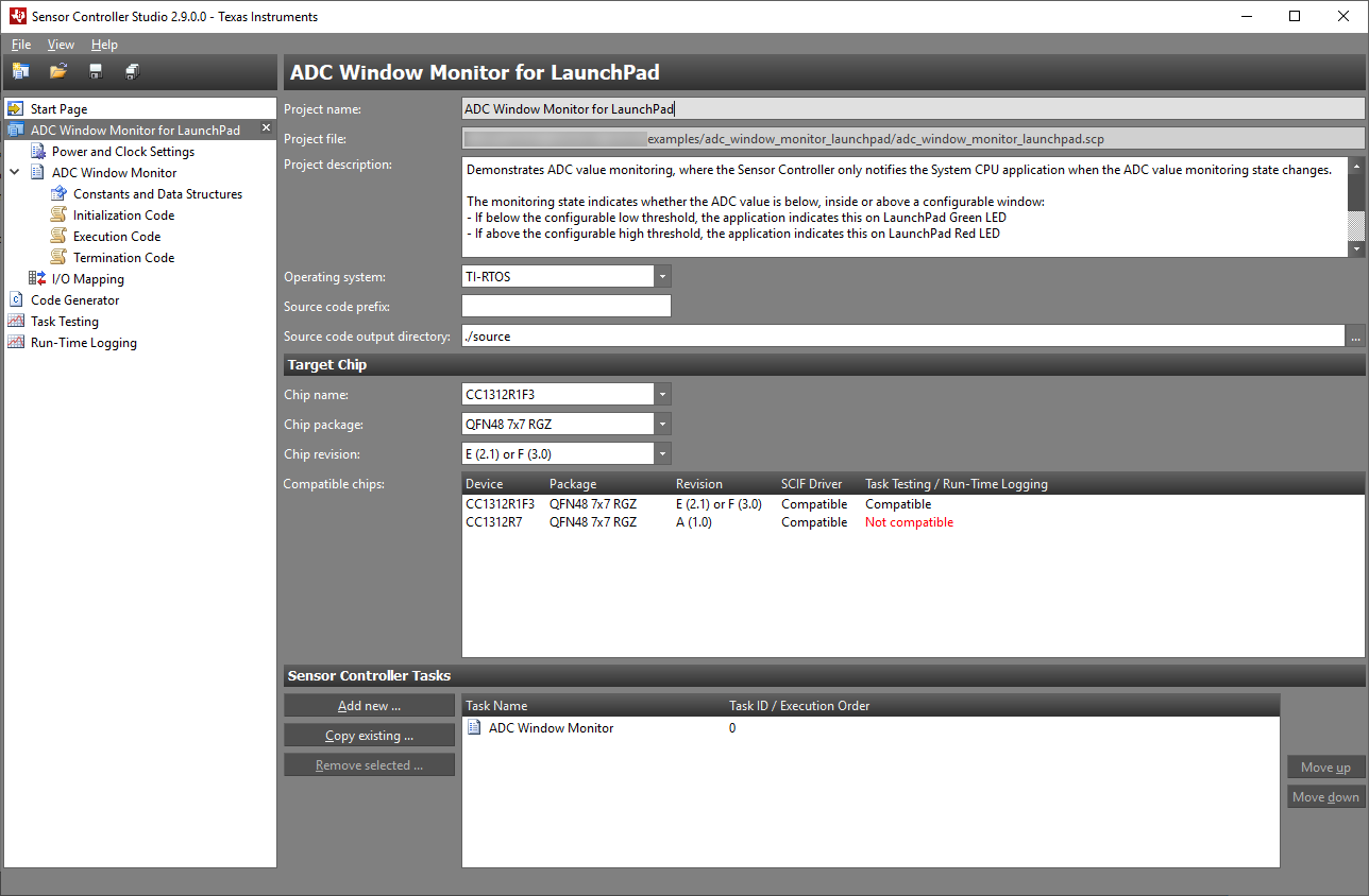
The project panel contains settings that apply to the entire project, and allows for tasks to be added and removed (see Figure 6-4).
 Figure 6-4 Project Settings
Panel
Figure 6-4 Project Settings
PanelThe project settings include:
- Project name and description: These are included in the generated SCIF driver setup header file.
- Operating system: Select the operating system that affects which SCIF OSAL files are output.
- Source code prefix (optional): If needed, specify a prefix that will be added to relevant parts of the driver setup (including file names). This allows for multiple SCIF driver setups in one application.
- Source code output directory: Specify the path of the generated output by the absolute path or path relative to the Sensor Controller project file (*.scp).
- Target chip: Select the target chip by specifying name, revision, and package. These settings affect which task resources are available, I/O mapping, task testing, and runtime logging.
Sensor Controller tasks can be added to and removed from the project in the bottom section.
It is possible to have multiple projects open at the same time.
Note:
The Save project and Close project commands apply only to the currently selected project in the project tree.