SWRU467A February 2017 – June 2018 CC3120
-
CC3120 SimpleLink™ Wi-Fi® Internet-on-a chip™ Solution SDK Getting Started Guide
- Trademarks
- 1 Introduction
- 2 Prerequisites
- 3 Board Configuration
- 4 Programming the CC3120 BoosterPack™
- 5 Getting Started With the MSP-EXP432P401R LaunchPad™
- 6 Getting Started With SimpleLink™ Studio
- Revision History
3.1 Board Setup For Programming
To program the CC3120BOOST or BOOSTXL-CC3120MOD board, the CC31XXEMUBOOST debug board is required. The CC31XXEMUBOOST board uses an FTDI chipset, which connects to the CC3120 through UART for programming purposes, and also connects to the reset line for automatic reset. The CC31XXEMUBOOST debug board is required for programming only.
Figure 1, Figure 2, and Figure 3 show how to properly configure the jumpers on the CC3120BOOST or BOOSTXL-CC3120MOD and CC31XXEMUBOOST boards.
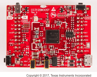 Figure 1. CC3120BOOST Board With Jumper Configuration
 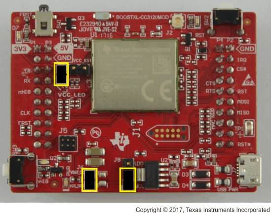 Figure 2. BOOSTXL-CC3120MOD Board With Jumper Configuration
 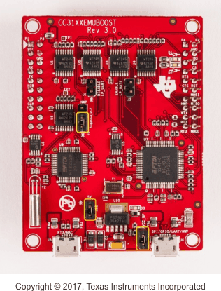 Figure 3. CC31XXEMUBOOST Board With Jumper Configuration
 Figure 4 shows how to mount the CC3120BOOST board on top of the CC31XXEMUBOOST board. Figure 5 shows how to mount the BOOSTXL-CC3120MOD on top of the CC31XXEMUBOOST board. Ensure P1.1 of both boards are aligned with each other, as indicated by the yellow arrows on both boards. The LDO and MCU jumper (J8) configuration is used for choosing the power source. This guide uses the MCU configuration. To supply power directly to either of the BoosterPack boards, change the jumper to LDO, and connect USB PWR (J7) with a USB cable.
 Figure 4. CC3120BOOST Board Mounted on Top of CC31XXEMUBOOST Board
 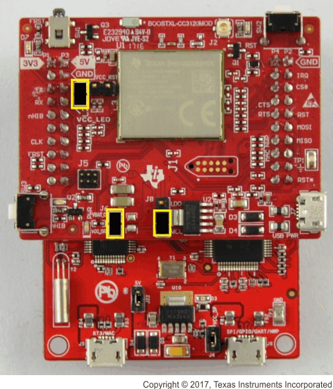 Figure 5. BOOSTXL-CC3120MOD Mounted on Top of CC31XXEMUBOOST
 To power the platforms, connect the J6 port of the CC31XXEMUBOOST board to the Windows PC using the micro USB cable (see Figure 6).
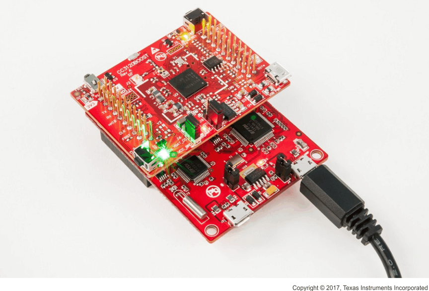 Figure 6. Powering the Platforms
 If the drivers are properly installed as mentioned during the SDK installation, then the PC should recognize and list the connected device in the Device Manager (see Figure 7). The boards are now ready for programming.
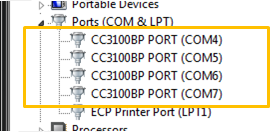 Figure 7. Device Manager Showing Ports