SWRU556 June 2021 CC3100 , CC3200
7.2 GUI TX Testing
Table 7-1 lists the three types of TX testing that are supported.
Table 7-1 TX Testing
| Type | Description |
|---|---|
| Packetized | Each packet is sent one at a time from the application MCU to the network processor. A large delay between packets exists in this mode. This mode is generally used for RF evaluation. |
| Continuous | This is a test mode where the network processor sends packets back to back in an internal loop, without the intervention of the host MCU. The delay between packets is typically very small, and hence useful for FCC/ETSI certification purposes where high-duty cycle is required. This mode is used only for emission certification. |
| Carrier Wave (CW) | In this mode the device transmits an unmodulated RF tone. The frequencies can be selected in 312.5-kHz steps. The power output with tone 0 is very low. If higher RF power is desired, use tone numbers other than 0. |
Some fields are enabled or disabled depending on the type of test being run. For example, the Amount parameter is disabled only when the Continuous testing type is selected.
Table 7-2 lists parameter explanations.
Table 7-2 Parameter Explanation
| Parameter | Range (inclusive) | Description |
|---|---|---|
| Channel | [1, 13] | 802.11 2.4-GHz band Wi-Fi channels. 14 is not supported. |
| [36..165] | 5-Ghz channels are enabled only for devices: CC3235x, CC3135 | |
| Power level | [0 to 15] | 0 is the maximum power, and 15 is the minimum
power. For 5-Ghz channels this parameter has no affect and the actual output power will be set to 0. |
| Tone | [-25, 25] | CW only. 0 is tone at center frequency. A value N between and within the range [–25, 25] means tone at offset N*312.5 kHz. |
| Rate | 802.11 PHY data rate. 5Ghz channels has no support
for DSSS and CCK rates. Supported:
|
|
| Preamble | [Long, Short] | 802.11b preamble. OFDM preamble is automatically configured by the device when OFDM rates are selected. |
| Data pattern | Data pattern in the data field. Supported:
|
|
| Size | [24, 1400] | Packet size in bytes |
| Delay | [100 to 1,000,000] | Delay of transmission in milliseconds (ms) |
| Amount | [0 to 1,000,000] | Number of packets to transmit. A value of 0 indicates infinite number of packets. |
| Override CCA | Enable this field for CCA (Clear Channel Assessment) override if the Wi-Fi environment is too congested to have a reliable periodic transmission. | |
| CCA threshold | The channel is considered occupied when the signal
strength is above this setting. Supported:
|
|
| Destination MAC address | Destination MAC address in packets | |
| Country | Sets device country code. Supported: US, EU, JP. For devices CC3135 and CC3235x there are additional country codes options. There is an option to select "No Limits" to remove all channel limitations or "00" for minimal limits. |
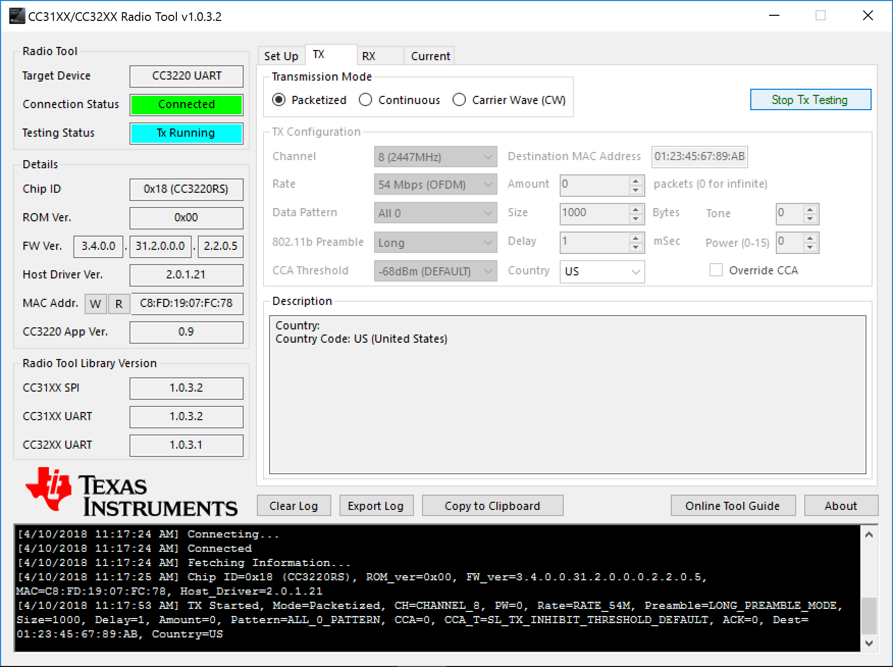
Figure 7-2 shows the Radio Tool GUI in the TX Tab.
 Figure 7-2 Radio Tool GUI in TX
Tab