SWRU580 April 2021 CC2564C , CC2564MODA , CC2564MODN
- Trademarks
- 1 Introduction
- 2 A2DP (AUD) Demo Guide
- 3 A3DP Sink Demo Guide
- 4 A3DP Source Demo Guide
- 5 HFP Demo Guide
- 6 HFP Audio Gateway Demo Guide
- 7 HID Demo Guide
- 8 HSP Demo Guide
- 9 Map Demo Guide
- 10PBAP Demo Guide
- 11SPP Demo Guide
- 12SPPLE Demo Guide
- 13SPPDMMulti Demo Guide
- 14ANP Demo Guide
- 15HFP Demo Guide
- 16HTP Demo Guide
- 17PASP Demo Guide
- 18HOGP Demo Guide
- 19PXP Demo Guide
- 20FMP Demo Guide
- 21CSCP Demo Guide
- 22Revision History
21.2 Demo Application
This section provides a description of how to use the demo application to connect two configured boards and communicate over bluetooth. Bluetooth CSCP is a simple Client-Server connection process. We will setup one of the boards as a Server and the other board as a Client. We will then initiate a connection from the Client to the Server. Once connected, we can transmit data between the two devices over bluetooth.
Server setup on the demo application- We will setup the first board as a Server. Note the bluetooth address of the Server; we will later use this to initiate a connection from the Client.Up to four commands are all that is needed to setup the CSCS Server.
- The first command we need is
RegisterCSCS, this command will register the service and initiate the Server,
issue the RegisterCSCS command.
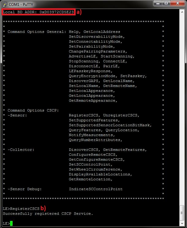 Figure 21-2 CSCP Demo CSCS
Register
 - In order to set the supported
features we issue the SetSupportedFeatures <Wheel Measurement Support>
<Crank Measurement Support> <Multiple Location Support>.Issue the SetSupportedFeatures 1 1 1 command to enable all features, the terminal will display a note that indicates the we need to issue the GetRemoteFeatures command in the Client's terminal.
 Figure 21-3 CSCP Demo STM32 Set
Supported Features Usage
 - If Multiple Location is
supported, in order to set the supported sensor locations list we issue the
SetSupportedSensorLocationBitMask <BitMask> command, which is a
bitmask that will enable the supported locations in the Server.Issue the SetSupportedSensorLocationBitMask 0x7fff command to set all the available locations in the list, the terminal will display that the update was successful.
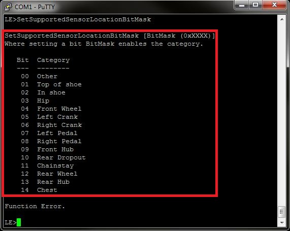 Figure 21-4 CSCP Demo CSCS Set
Supported Sensor Location Bit Mask Usage
 - Now, after we configured the
Server, we can begin advertising to nearby devices by issuing the AdvertiseLE
1 command.
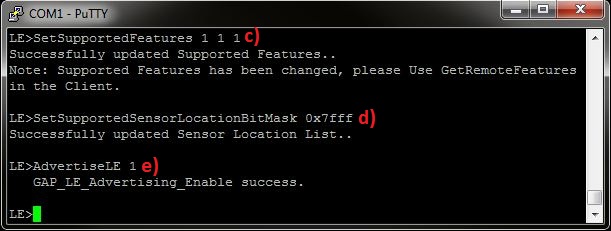 Figure 21-5 CSCP Demo CSCS
Features and Location
- The Client LE device can try to find which LE devices are in the vicinity by issuing the StartScanning command.
- Once you have found the device,
you can stop scanning by issuing the StopScanning command.
 Figure 21-6 CSCP Demo STM32 Start
Scanning
 - Retrieve the Bluetooth address of the first board that was configured as a Server.
- Issue a ConnectLE <BD_ADDR of Server> command in the Client terminal.
- When a Client successfully
connects to a Server, both the Client and Server will output
LE_Connection_Complete notification and information about the current
connection.Discovering and Configuring the Server
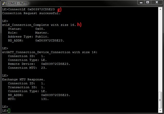 Figure 21-7 CSCP Demo STM32 Client
Connect LE
Figure 21-7 CSCP Demo STM32 Client
Connect LENow we have a connection established and both devices are ready to send data to each other. Before Cycle Speed and Cadence information can be sent we must first initialize commands in the Client terminal.
- In order to discover The service
handles we issue the DiscoverCSCS command and the handles that are
discovered will be displayed in the terminal.
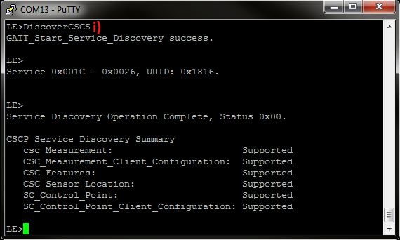 Figure 21-8 CSCP Demo STM32
Discover CSCS
 - After discovering the handles we need to discover the supported features of the
Server, so we issue the GetRemoteFeatures command, which will display the
supported features in the Client terminal.
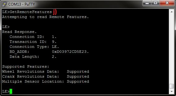 Figure 21-9 CSCP Demo STM32 Get
Remote Features
 - In order to enable Server
notifications, and if the SC Control Point exists also enable indications we
issue the ConfigureRemoteCSCS 1 command in the Client's terminal. If the
configuration succeeds information about the CCCD configuration will be
displayed in the Client and Server terminals.
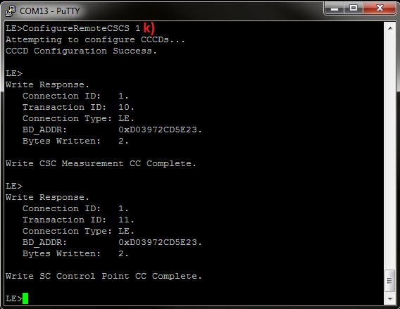 Figure 21-10 CSCP Demo STM32
Configure Remote Enable
Now we have a connection established and both devices configured and are ready to send data to each other.
We can now notify from the Sensor (Jump to paragraph t) or we can send SC Control Point Command to the sensor from the collector (next paragraph).
In Client Terminal:
- When we make new connection
between collector and Sensor we need to Set the wheel circumference so the
collector will be able to calculate Instantaneous speed, so we issue the
SetWheelCircumference <Circumference> command to set the
circumference in cm. Type SetWheelCircumference 210 in order to set wheel
circumference of 210 cm.
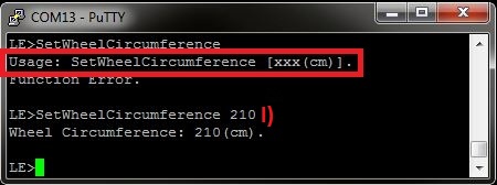 Figure 21-11 CSCP Demo STM32 Set
Wheel Circumference
 - When we want to change data in
the sensor we can do it only from the collector by issuing the
SetSCControlPoint command. We can update the cumulative wheel
revolutions, the sensor location or retrieve a list of supported sensor
locations using this command. After each command the collector will receive a
response indication from the sensor.
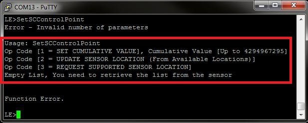 Figure 21-12 CSCP Demo STM32 Set SC
Control Point Usage
 - If we want, and only when we
support wheel revolutions, we can update the cumulative wheel revolutions using
the SC Control Point Command. To do so we issue the SetSCControlPoint 1
<Cumulative value to update> command, for example type
SetSCControlPoint 1 2000.
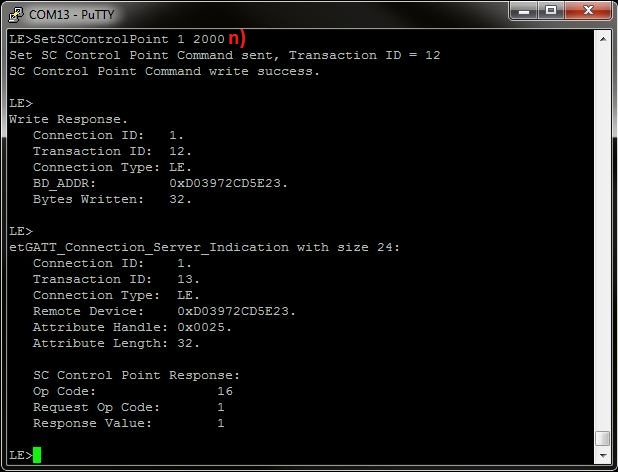 Figure 21-13 CSCP Demo Set SC
Control Point
 - If we want to change sensor
location, and only if we support multiple sensor location, we can change it only
to locations that the sensor supports. To see the supported locations list, we
issue the DisplayAvailableLocations command. If the list is empty we need
to retrieve it first, we will do so in the next paragraph. If the list isn't
empty jump to paragraph "p".
 Figure 21-14 CSCP Demo STM32
Display Available Locations
 - In order to retrieve the sensor location list, and only when we supported multiple sensor location, we need to use the set SC Control Point command which retrieve the list, to do so we use SetSCControlPoint 3. Type SetSCControlPoint 3 and you will see the available sensor locations.
- You can see confirmation for the
command and the indication from the sensor that includes the list.
 Figure 21-15 CSCP Demo STM32 Set SC
Control Point 2
 - After the collector has the
sensor supported list locations, the collector can update the sensor location
using SetSCControlPoint 2 and the number of the location from the list
that we want to update, type SetSCControlPoint 2 3.In Server Terminal:
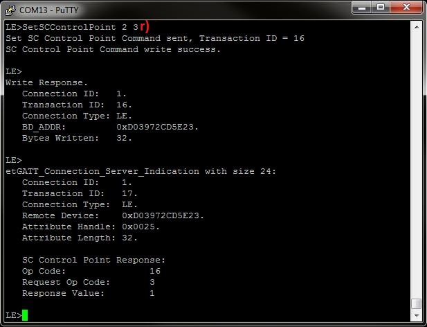 Figure 21-16 CSCP Demo STM32 Set CS
Control Point 3
 - After we set new sensor location,
we can check it by issuing the Querylocation command and you will be able to see
the new location.
 Figure 21-17 CSCP Demo STM32 Query
Location
 - Now, when we finish with all the
configurations and command the sensor can start notifying his measurements, in
order to do so, we issue the NotifyMeasurements command. When the sensor
support only wheel revolutions or crank revolutions you need to input 2
parameters, cumulative value, and time event value, when both are supported you
need to input 4 parameters wheel cumulative value, wheel time event value, crank
cumulative value and crank time event value.
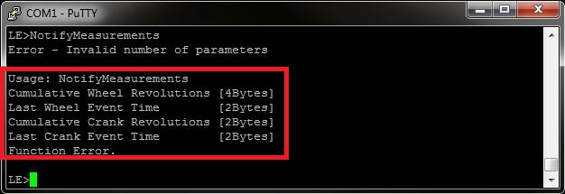 Figure 21-18 CSCP Demo STM32 Notify
Usage
 - In this example wheel revolutions
and crank revolutions are supported. then type NotifyMeasurements 2008 64000
65534 9300, you will be able to see on the Client terminal the
parameters you entered.
- Server Terminal
 Figure 21-19 CSCP Demo
STM32 Notify
 - Client Terminal
- The Calculation for
instantaneous speed
Speed[cm/(s/1024)] = (Difference in two successive Cumulative Wheel Revolution values * Wheel Circumference) / (Difference in two successive Last Wheel Event Time values) In order to receive Speed[km/h] we need to multiple the result with (3.6*1024/100) - The Demo is doing the calculation for us when we use DISPLAY_DEBUG definitions in the environment
- The Calculation for
instantaneous cadence
Cadence[r/(s/1024)] = (Difference in two successive Cumulative Crank Revolution values) / (Difference in two successive Last Crank Event Time values) In order to receive Cadence[rpm] we need to multiple the result with (60*1024) - The Demo is doing the calculation for us when we use DISPLAY_DEBUG definitions in the environment
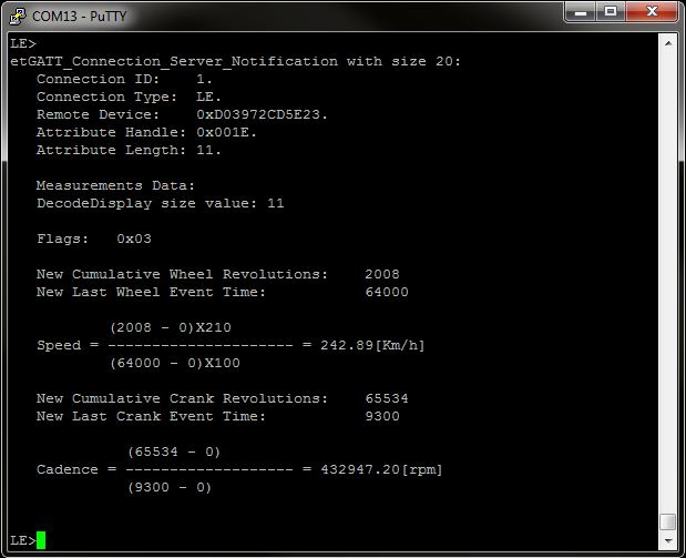 Figure 21-20 CSCP Demo STM32 Notify
Client
 - Server Terminal
- When using debug mode, the
application will calculate the Instantaneous Speed and Instantaneous Cadence. In
order to do this calculation we need to send another notification. Type
NotifyMeasurements 2016 65024 65535 10324, now in the Client Terminal you can
see Instantaneous Speed [km/h] and Instantaneous Cadence [rpm].
- Server Terminal
 Figure 21-21 CSCP Demo
STM32 Notify 2
 - Client Terminal
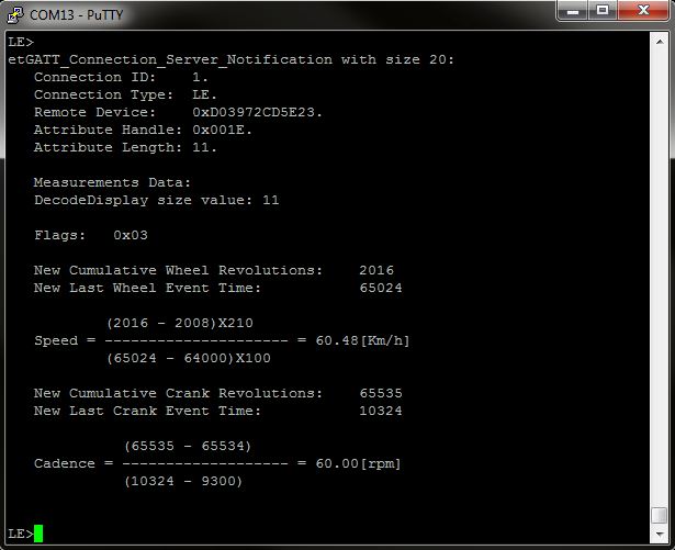 Figure 21-22 CSCP Demo STM32 Notify
Client 2
 - Server Terminal