SWRU598A June 2022 – April 2024 AWR1243 , AWR1642 , AWR1843 , AWR2243 , AWR2944 , AWR6443 , AWR6843 , AWRL1432 , AWRL6432 , IWR6843
2.2 Step-2 : Typical System Block Diagram
In this second step of the functional safety design life cycle with the understanding of PRD and blocks/ subsystems, the customer will refer to a typical system block diagram based on the end application. For reference block diagram of FuSa compliant Radar sensor system, the customer can refer to the TI mmWave Radar EVM's and TI Reference Designs. This step includes the hazard and risk analysis, a crucial and necessary part for determining safety integrity levels(ASIL-A/B/C/D, SIL-1/2/3/4) that sets the tone for system FuSa journey.
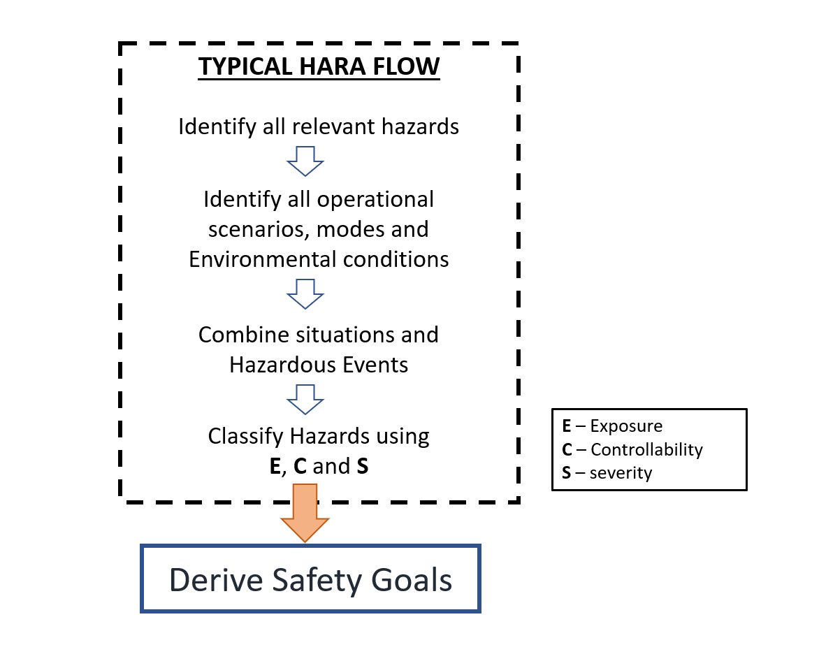
The hazard and risk analysis is performed on the reference block diagram. The safety requirements for automotive system application are formulated from Hazard Analysis and Risk Assessment(HARA) as per ISO 26262 standard requirement using metrics Exposure(E), Controllability(C) and Severity(S). For deriving safety goals in industrial domain system applications, there is no specific process/assessment to be followed as per IEC 61508 standard. So, typical HARA flow can be followed for determining the safety goals using metrics E,C and S.
Please note that compliance of AEC-Q100 standard is also important to electronic systems being developed for usage in Automotive applications. The typical HARA flow is shown in the following Figure 2-3.
 Figure 2-3 Typical HARA flow
The typical system block diagram of any FuSa compliant sensor system would consists of
- mmWave Radar Sensor
- RF Block
- Antennas
- External Crystal Oscillator
- Power Supply - PMIC / Discrete DC based power level converters
- Communication Interfaces
- Debugging and Development Interfaces
- Flash Interface
- PM Components
The mmWave Radar sensor system should support different interfaces like communication interfaces for data transfer, debugging and development interfaces for debugging and flash interfaces for externally flashing the device. RF antennas are used for the transmission and receiving of chirp signals for detection. Oscillator in the RF block is used to generate clock frequency. Power is supplied using power supply blocks like PMIC or discrete DC based power level converters for different power rails.
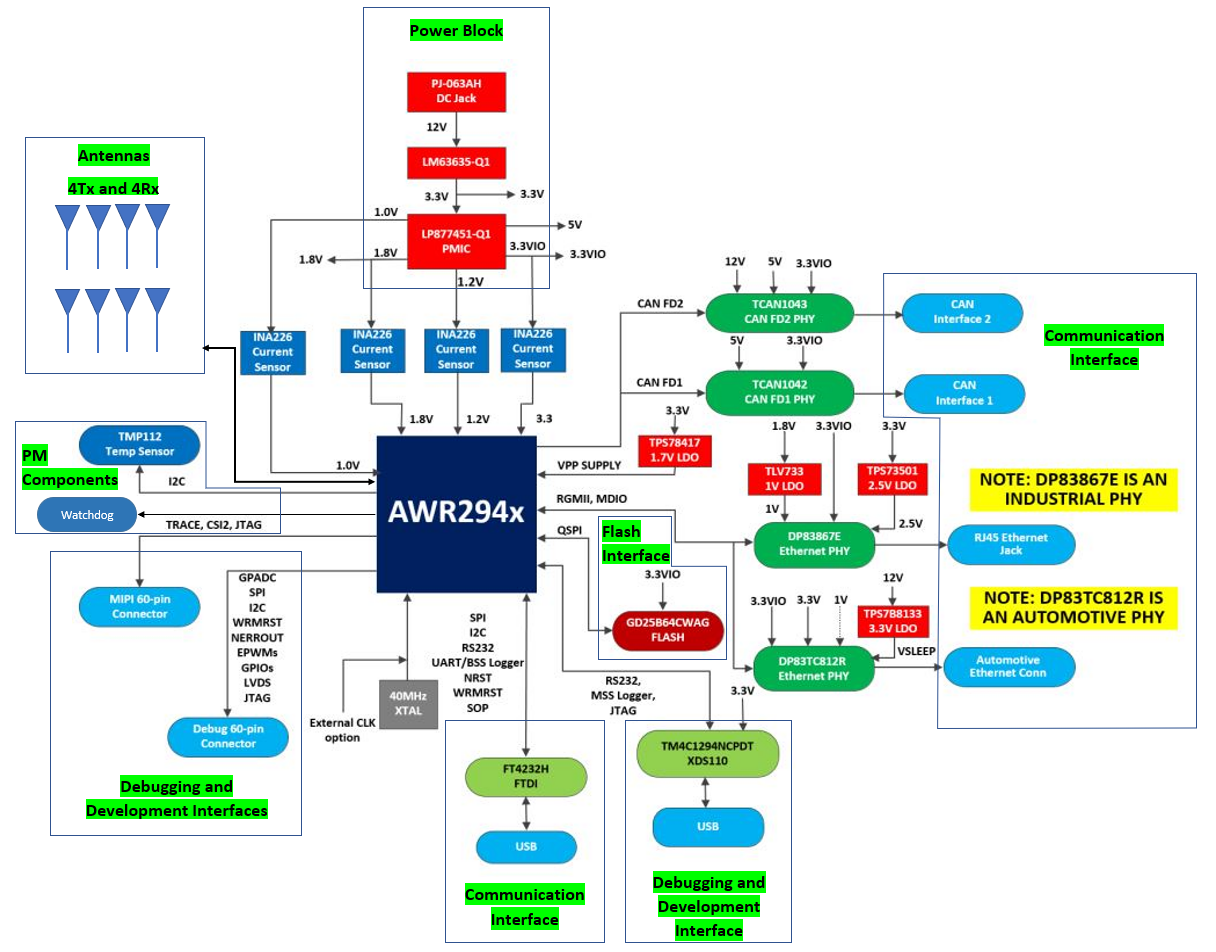
For ex., to design a high-performance corner radar system, AWR2944 mmWave Radar sensor, PMIC and CAN interface could be used. The customer can refer to AWR2944 EVM designed by TI for typical system block diagram, also mentioned in Figure 2-4.
 Figure 2-4 AWR2944 EVM
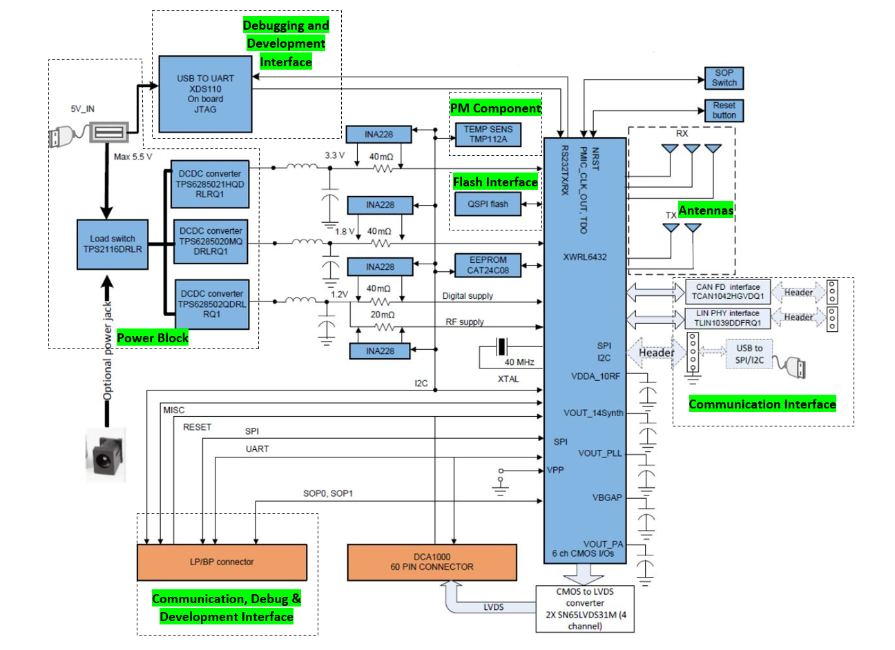
Similarly, to create an intelligent robot sensing system for safer human presence detection, IWRL6432 mmWave Radar sensors can be used by considering IWRL6432 EVM as a reference to the typical system block diagram, also mentioned in Figure 2-5. In this example, we are considering coverage of single sensor. For 3600 safer human presence detection, multiple IWRL6432 mmWave Radar sensors could be used for covering the total perimeter of industrial robot.
 Figure 2-5 IWRL6432 EVM
Safety goals are determined by assessing the system block diagram. Some additional hardware safety mechanisms might be added in its design to meet targeted safety goals. If the safety goals are still not meeting the targeted safety requirements after modifying block diagram then the customer has to look up for refining the safety end equipment requirements.
Along with the safety requirements and goals identification, there are certain additional critical analysis (For ex., DFA and Coexistence Analysis) needed from a system level integration perspective. Dependent Failure Analysis(DFA) is performed on the system to identify Common Cause Failures(CCF) and Cascading Failures in the system. For the most cost-effective FuSa compliant system, the multiple safety mechanisms implemented in the system may have different applicable safety integrity levels(ASIL-A/B/C/D or SIL-1/2/3/4). Coexistence Analysis is performed on the system to detect or prevent the interference of high failure rate(Ex.: SIL-1, ASIL-A) subsystems driving low failure rate(Ex.: SIL-3, ASIL-C) subsystems, achieving Freedom From Interference(FFI). FFI is achieved through the prevention of cascading failures in a system, which is often accomplished via block partitioning the system to locate the failure origin and prevent its propagation to other system/subsystems. The first two steps of proposed FuSa design flow will be in a cyclic process starting with end equipment requirements and ends with a mature system block diagram that meets targeted end equipment requirements. The system block diagram is said to be mature only when the system block diagram meets end equipment requirements including safety requirements.
Key deliverables from the "Step-2: Typical system block diagram" of the proposed FuSa design life cycle is a mature system-level block diagram that meets the targeted end equipment requirements. Safety goals of the system are derived in this step by performing typical HARA on the block diagram. This step is one of the most crucial steps of designing functionally safe systems and sets a tone for the system FuSa journey by deriving the system application's safety goals.